Protecting structure for movable mechanism in a miniature lens

a technology of movable mechanism and protective structure, which is applied in the direction of mountings, optics, instruments, etc., can solve the problems of lens damage, lens becoming damaged or useless, lens just cannot afford to fall, etc., and achieve the effect of limiting the torsion force and limiting the elastic rang

Inactive Publication Date: 2009-01-08
TDK TAIWAN
View PDF2 Cites 15 Cited by
  • Summary
  • Abstract
  • Description
  • Claims
  • Application Information

AI Technical Summary

Benefits of technology

[0007]A primary object of the present invention is to provide a protecting structure for movable mechanism in a miniature lens, so that elastic members in a movable miniature lens focusing mechanism are protected against deformation.
[0008]To achieve the above and other objects, the protecting structure for movable mechanism in a miniature lens according to the present invention is mounted in a housing of a miniature lens focusing mechanism, and includes an upper cover, a lens holder, at least one elastic member, and at least one protective member. The lens holder is configured to hold a lens therein. The at least one elastic member connects the lens holder to the upper cover, so that the lens holder is supported by the elastic member to suspend in the housing and is axially displaceable forward or rearward for focusing. The protective member is located outside the elastic member relative to the lens holder and received in a central opening of the upper cover for restricting the lens holder from displacing laterally, and limiting the torsion force produced at the time of screwing the lens into the lens holder, so as to protect the elastic member against deformation.
[0009]In the present invention, the upper cover is provided with at least one notch, and the protective member is provided with at least one tongue corresponding to the notch on the upper cover. The protective member is received in the central opening of the upper cover with the at least one tongue engaged with the at least one notch, so as to limit an extent within which the elastic member can be turned or horizontally moved.

Problems solved by technology

Under this condition, a lens just could not afford to fall because a big impact due to falling would cause the lens to displace laterally and result in damage of the elastic members.
That is, the lens would become damaged or useless due to lack of elastic protection in the lateral directions.

Method used


Image

  • Protecting structure for movable mechanism in a miniature lens
  • Protecting structure for movable mechanism in a miniature lens
  • Protecting structure for movable mechanism in a miniature lens

Examples


Embodiment Construction

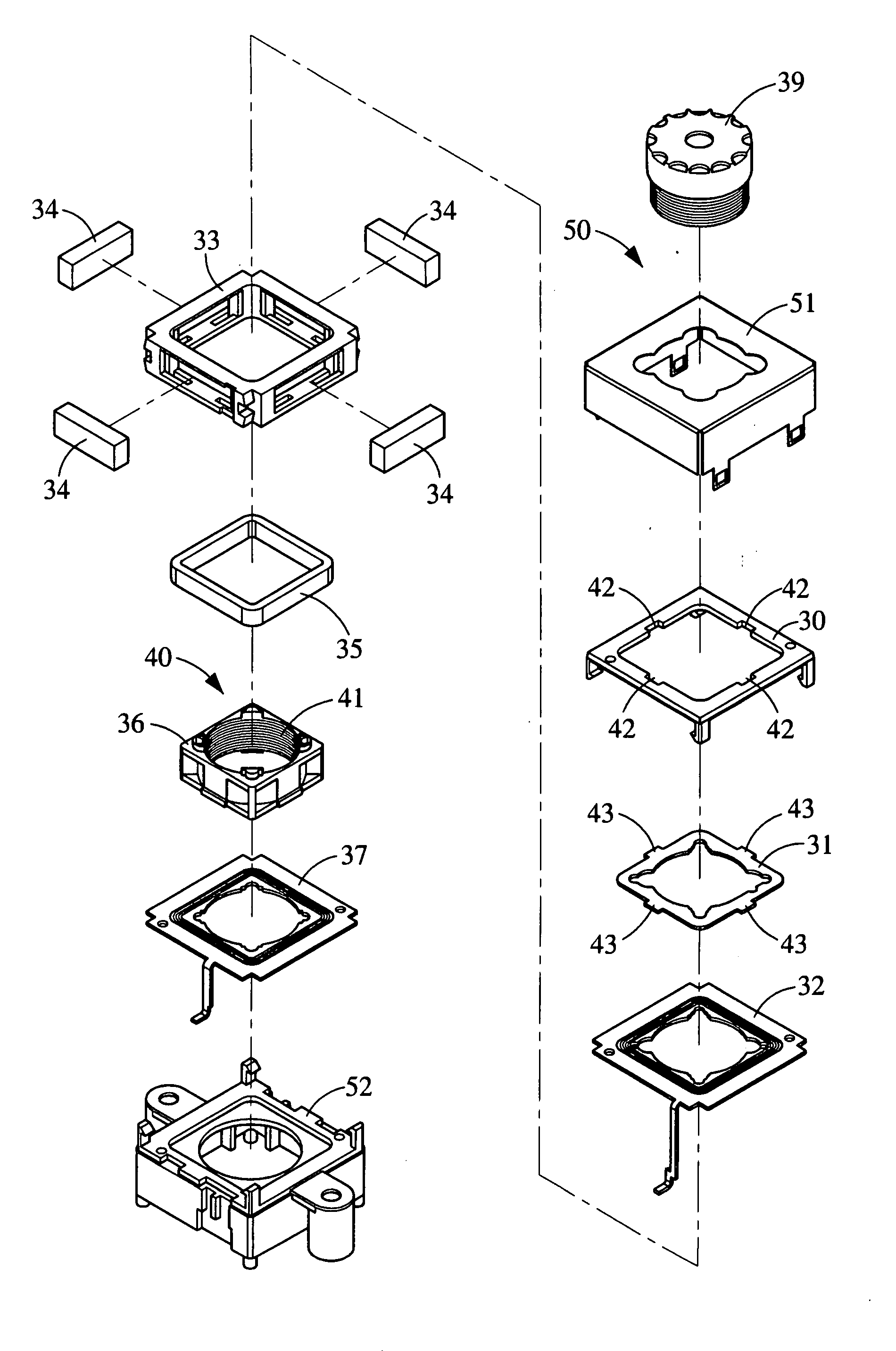
[0016]Please refer to FIG. 3 that is an exploded perspective view of a protecting structure for movable mechanism in a miniature lens according to the present invention mounted in a housing 50 of a focusing mechanism of the miniature lens. The housing 50 consists of an upper case 51 and a base 52, and the present invention is received in the upper case 51. As shown, the protecting structure of the present invention includes an upper cover 30, a protective member 31, a first elastic member 32, a frame 33, a plurality of magnetic elements 34, a winding 35, a lens holder 36, and a second elastic member 37. The lens holder 36 is a hollow ring member defining a through hole 40, on a peripheral wall thereof screw threads 41 are provided, so that a lens 39 may be correspondingly screwed into the lens holder 36.

[0017]FIG. 4 is an assembled perspective view of FIG. 3 with the lens 39 and the upper case 51 omitted therefrom. As shown, the upper cover 30 defines a central opening, along a peri...


PUM


Abstract

A protecting structure for movable mechanism in a miniature lens is mounted in a housing of a focusing mechanism of the miniature lens and includes an upper cover defining a central opening and fixed in the housing; a lens holder for holding a lens therein; at least one elastic member connecting the lens holder to the upper cover, so that the lens holder is suspended in the housing and axially displaceable forward and rearward to achieve the purpose of focusing; and at least one protective member being received in the central opening of the upper cover to locate outside the elastic member relative to the lens holder for restricting the lens holder from moving laterally, and limiting a torsion force produced at the time of screwing the lens into the lens holder, so as to protect the elastic member against deformation due to the torsion force.

Description

FIELD OF THE INVENTION[0001]The present invention relates to a protecting structure for movable mechanism in a miniature lens, and more particularly to a structure for protecting elastic members in a miniature lens focusing driving mechanism against deformation.BACKGROUND OF THE INVENTION[0002]With the advancement in scientific technologies and the modularization and miniaturization of camera lens, it is now possible to produce digital cameras having a very small volume, and most of currently available mobile phones are provided with the function of a digital camera. In a miniature lens, there are many different auto-focusing driving mechanisms. Among others, voice coil motor (VCM) is the currently most widely adopted auto-focusing driving mechanism. The VCM has the advantages of small volume, low power consumption, accurately actuated displacement, and cost-effective, and is therefore very suitable for short-distance driving in miniature lens auto-focusing.[0003]FIG. 1 is an explod...

Claims


Application Information

Patent Timeline
Patent Type & Authority Applications(United States)
IPC IPC(8): G02B7/04
CPCG02B7/08
Inventor WANG, HUNG-LIN
Owner TDK TAIWAN
Why Eureka
Try Eureka