Heat recovery system

a heat recovery and heat recovery technology, applied in the direction of heat exchange apparatus safety devices, machines/engines, light and heating apparatus, etc., can solve the problems of condensed emission, vaporization of liquid heat exchange medium, condensation of moisture or water content, etc., to improve heat recovery efficiency and reduce wall thickness

Inactive Publication Date: 2012-09-18
THE UNIV OF TOKYO +3
View PDF25 Cites 7 Cited by
  • Summary
  • Abstract
  • Description
  • Claims
  • Application Information

AI Technical Summary

Benefits of technology

[0007]In the heat recovery system according to this aspect of the invention, during warm-up of the internal combustion engine, the shutoff valve is closed to shut off the flow of the emission through the emission flow conduit. In this state, the emission of the internal combustion engine flows in through the non-contact areas that are not blocked by the emission inflow-side end plate, is supplied to the intervals of the respective flat tubes in the tube stack, passes through the non-contact areas that are not blocked by the emission outflow-side end plate, and flows out to be discharged to the downstream. The heat exchange medium, on the other hand, flows in from the heat exchange medium supply pipe to one of the at least two communication paths provided in the tube stack, is supplied into the respective flat tubes in the tube stack, is heated by means of heat exchange with the emission flowing through the intervals of the respective flat tubes, passes through the other of the at least two communication paths, and flows out to the heat exchange medium recovery pipe to be recovered. The recovered hot heat exchange medium may be supplied, for example, to a heat exchange unit for heat exchange with the flow of cooling water through the internal combustion engine to accelerate the warm-up of the internal combustion engine. After completion of the warm-up of the internal combustion engine, the shutoff valve is opened to release the shutoff of the emission flow through the emission flow conduit. In this state, the emission of the internal combustion engine is not supplied to the tube stack but flows through the emission flow conduit to be discharged to the downstream. In the heat recovery system according to this aspect of the invention, the tube stack used for heat exchange is created by stacking multiple flat tubes formed in a flat, substantially donut shape with high density. This arrangement desirably attains the small-sized, high-performance heat recovery system. In the heat recovery system of the invention, the shutoff valve is provided in the emission flow conduit. During warm-up of the internal combustion engine, the shutoff valve is closed to shut off the flow of the emission through the emission flow conduit. This arrangement assures the efficient recovery of heat from the emission at a start of the internal combustion engine. The emission flow conduit is arranged to be in contact with the inside of the tube stack and to have the heat insulating effect. After completion of the warm-up of the internal combustion engine, the shutoff valve is opened to release the shutoff of the emission flow through the emission flow conduit. This arrangement effectively prevents the heat exchange medium from being overheated by the high-temperature emission of the warmed-up internal combustion engine.
[0008]In one preferable application of the heat recovery system according to the above aspect of the invention, one of the emission inflow-side end plate and the emission outflow-side end plate is attached to the casing with being bonded to one end of the tube stack, and the other of the emission inflow-side end plate and the emission outflow-side end plate is attached to the casing without being bonded to the other end of the tube stack. Even when the casing and the tube stack have different rates of thermal expansion, this arrangement desirably reduces the effect of a stress potentially applied to the tube stack, compared with a conventional arrangement where both the emission inflow-side end plate and the emission outflow-side end plate are attached to the casing with being bonded to the tube stack. Namely this arrangement effectively protects the tube stack from the potential deformation or damage due to application of the stress, thus enhancing the durability of the heat recovery system.
[0010]In still another preferable application of the heat recovery system according to the above aspect of the invention, the heat exchange medium supply pipe and the heat exchange medium recovery pipe are attached either to the emission inflow end of the tube stack on the emission inflow side of the casing or to the emission outflow end of the tube stack on the emission outflow side of the casing. In one preferable structure of the heat recovery system of this application, one of the emission inflow-side end plate and the emission outflow-side end plate that is located on a side with the heat exchange medium supply pipe and the heat exchange medium recovery pipe may be attached to the casing with being bonded to the end of the tube stack. The other of the emission inflow-side end plate and the emission outflow-side end plate that is located on a side without the heat exchange medium supply pipe and the heat exchange medium recovery pipe may be attached to the casing without being bonded to the end of the tube stack. This arrangement desirably reduces the effect of a stress potentially applied to the heat exchange medium supply pipe and the heat exchange medium recovery pipe due to the different thermal expansion rates of the casing and the tube stack. Namely this arrangement effectively protects the heat exchange medium supply pipe and the heat exchange medium recovery pipe from the potential deformation or damage due to application of the stress, thus enhancing the durability of the heat recovery system.
[0011]In another preferable application of the heat recovery system according to the above aspect of the invention, the emission inflow-side end plate, the emission outflow-side end plate, and the tube stack are attached to the casing, such that the one non-contact areas of the at least two non-contact areas aligned in sequence in the tube stack and blocked by the emission inflow-side end plate are provided as lower non-contact areas located in a lower portion of the casing and the other non-contact areas of the at least two non-contact areas aligned in sequence in the tube stack and blocked by the emission outflow-side end plate are provided as upper non-contact areas located in an upper portion of the casing. Even when the water content in the emission condensed and flowed down in the form of dew drops in the process of heat exchange, this arrangement enables the condensed water to be flowed out to the downstream. In one preferable embodiment of the heat recovery system of this application, the at least two communication paths respectively aligned in sequence in the tube stack are arranged to make an upward flow of the heat exchange medium inside the respective flat tubes. This arrangement enables the overall flow of the heat exchange medium and the overall flow of the emission to be opposed to each other, thus enhancing the heat exchange efficiency of the heat recovery system.
[0012]In the heat recovery system of the invention with the arrangement where the one non-contact areas blocked by the emission inflow-side end plate are located in the lower portion of the casing and the other non-contact areas blocked by the emission outflow-side end plate are located in the upper portion of the casing, the casing may be structured to have an emission outflow path arranged to be substantially horizontal with or to be downward inclined relative to the lower non-contact areas blocked by the emission inflow-side end plate or may alternatively be structured to have an axis of an emission outflow path decentered downward relative to an axis of an emission inflow path. This arrangement enables the water content in the emission condensed and flowed down in the form of dew drops in the process of heat exchange to be readily discharged with the emission flow.
[0014]In one preferable embodiment of the heat recovery system according to the above aspect of the invention, the tube stack has fins provided in at least partial area between respective adjacent pairs of the multiple flat tubes. This arrangement desirably enhances the efficiency of heat recovery. In the heat recovery system of this embodiment, the fins may be provided to support the multiple flat tubes in the stacking direction. This arrangement desirably protects the individual flat tubes and the tube stack from deformation and allows for reduction of the wall thickness of the individual flat tubes.

Problems solved by technology

One issue to be solved is discharge of the moisture or the water content in the emission condensed in the course of heat recovery.
Another issue to be solved is vaporization of a liquid heat exchange medium in the course of heat exchange.

Method used


Image

  • Heat recovery system
  • Heat recovery system
  • Heat recovery system

Examples


Embodiment Construction

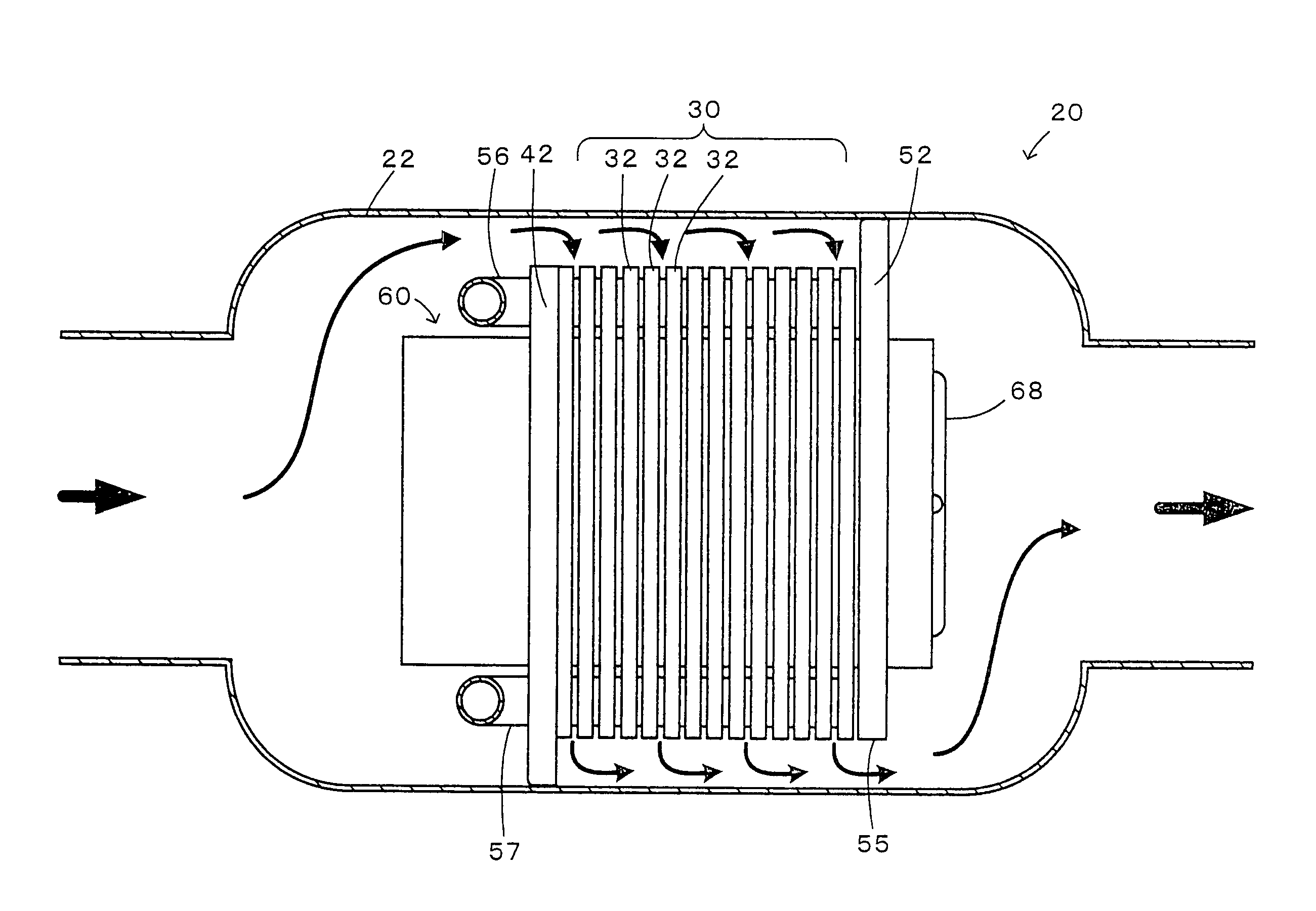
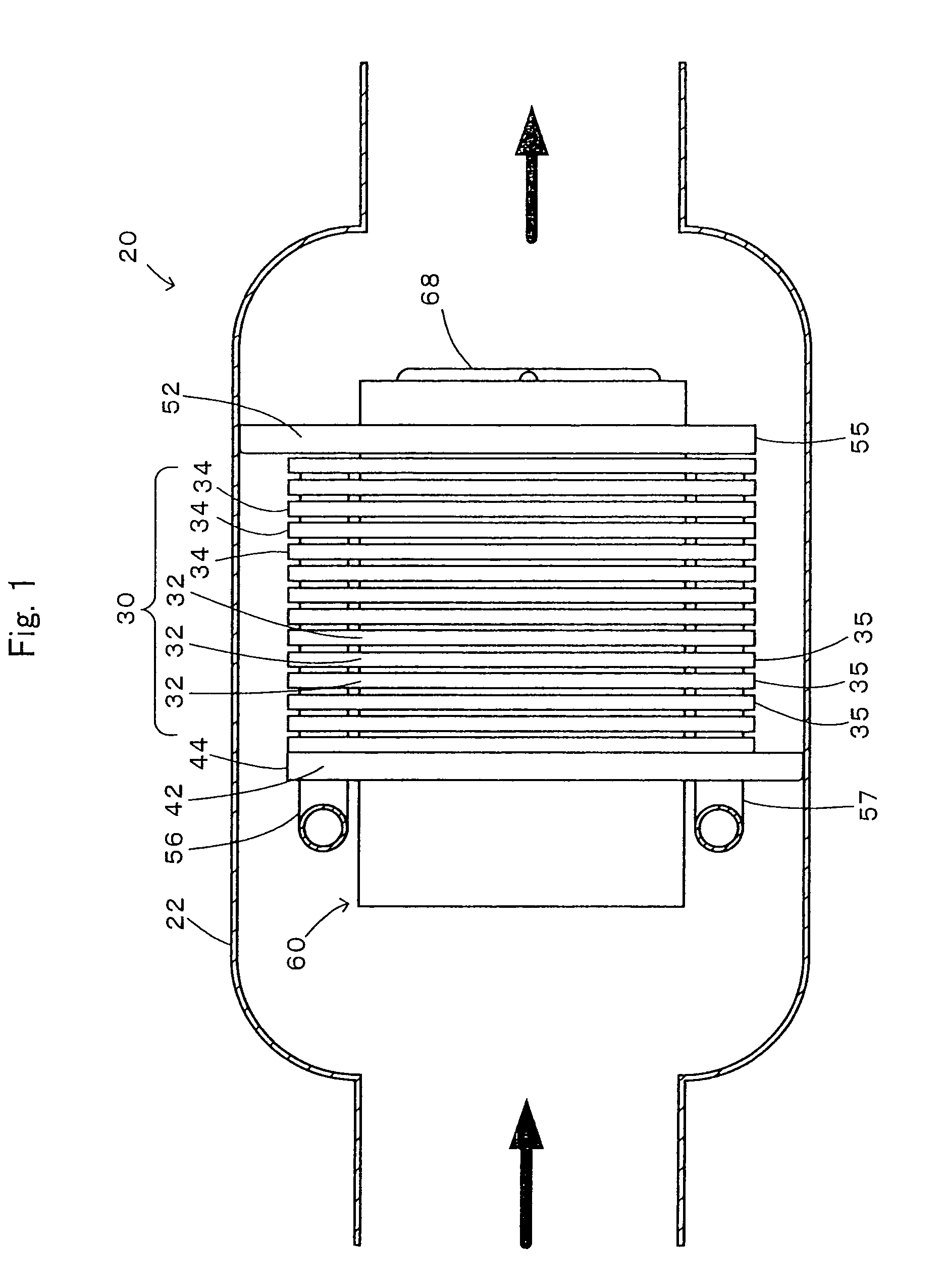
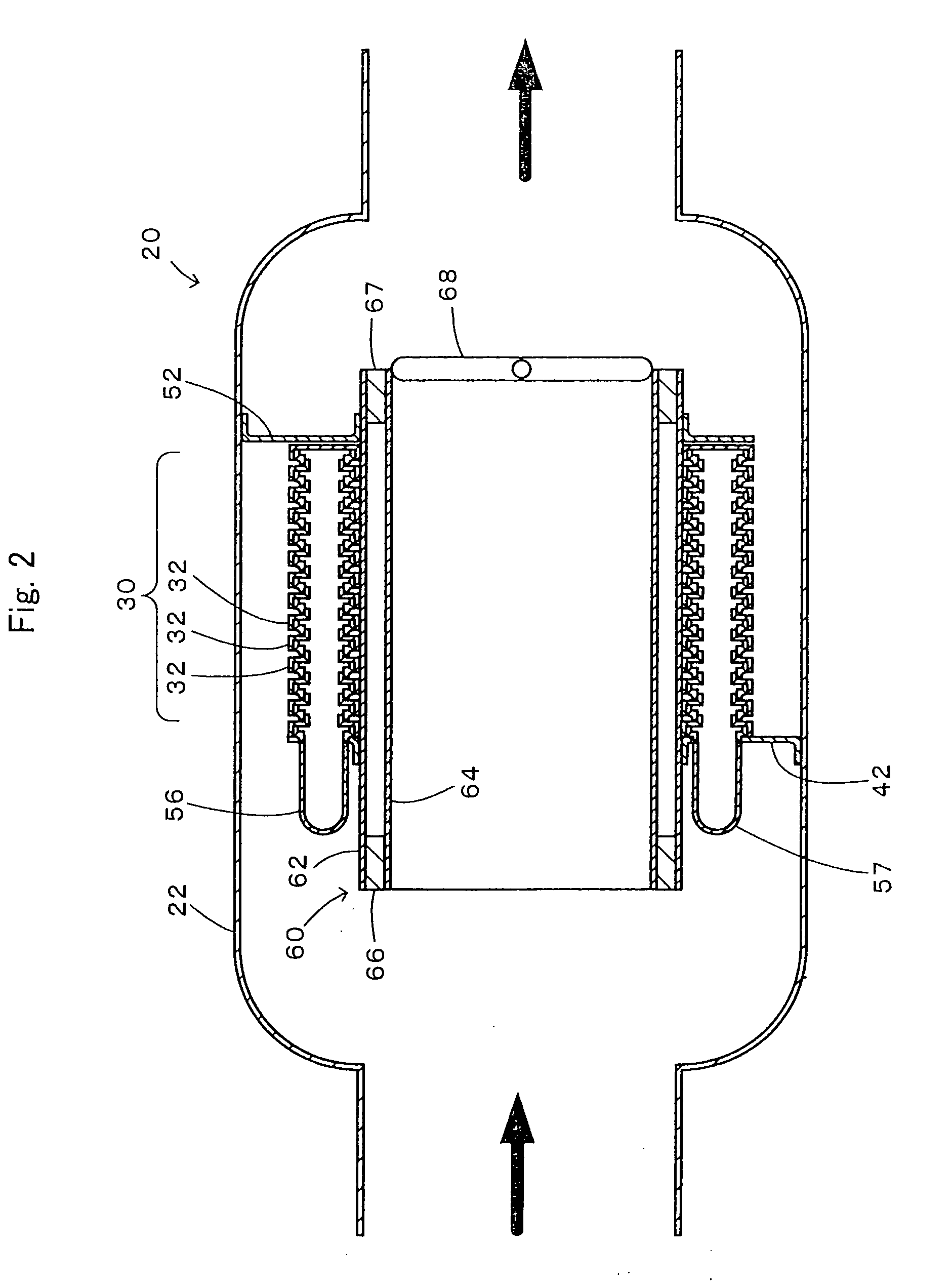
[0024]Some modes of carrying out the invention are described below with reference to the accompanied drawings. FIG. 1 is a diagrammatic representation of the general configuration of a heat recovery system 20 in accordance with one embodiment of the invention. FIG. 2 is a diagrammatic cross sectional view representation of the heat recovery system 20 of the embodiment. As illustrated, the heat recovery system 20 of the embodiment includes a casing 22 attached to an exhaust pipe of the internal combustion engine, a tube stack 30 created by stacking multiple donut-shaped, hollow flat tubes 32, an emission inflow-side end plate 42 attached to and bonded to one end flat tube 32 located on an emission inflow end of the tube stack 30 and fastened to the casing 22, an emission outflow-side end plate 52 arranged by a preset distance away from the other end flat tube 32 located on an emission outflow end of the tube stack 30 to be not in direct contact with the other end flat tube 32 and fas...


PUM


Abstract

A plurality of flat tubes formed as a tube having notches by linearly cutting upper and lower parts from a hollow flat circular doughnut shape are stacked to structure a tube laminate. It is attached to a case so that a notch aligns with the notch and faces upward by an exhaust inflow end plate and that a notch aligns with the notch and faces downward by an exhaust outflow end plate. A cutoff valve is provided at an exhaust outflow end of an exhaust communication tube passing through the center of the tube laminate by heat insulation. While an internal combustion engine is warming up, the cutoff valve is closed to cause the exhaust to flow in gaps of the respective flat tubes from upward to downward as a whole and also a heat exchange medium is caused to flow in the respective flat tubes from downward to upward as a whole to have heat exchanged between the exhaust and the heat exchange medium to recover the exhaust heat.

Description

TECHNICAL FIELD[0001]The present invention relates to a heat recovery system and more specifically pertains to a heat recovery system configured to recover heat from the emission of an internal combustion engine.BACKGROUND ART[0002]One proposed structure of a heat recovery system has a heat exchange path arranged to perform heat exchange between emission of an internal combustion engine and a heat exchange medium, a bypass path arranged to discharge the emission with bypassing the heat exchange path, and a heat insulating layer coaxially arranged with the heat exchange path and the bypass path and formed between the heat exchange path and the bypass path (see, for example, Japanese Patent Laid-Open No. 2007-32561). In this prior art heat recovery system, the heat insulating layer is formed around the outer circumference of the bypass path, and the heat exchange path is formed around the outer circumference of the heat insulating layer. A heat exchange medium flow path is further for...

Claims


Application Information

Patent Timeline
Patent Type & Authority Patents(United States)
IPC IPC(8): F01N5/02F01N13/08F01N13/14
CPCF01N5/02F28D7/0041F28D7/005F01N2240/02F28D21/0003F28F2250/06Y02T10/16F28F2265/26F28F2265/10Y02T10/12
Inventor SHIKAZONO, NAOKIMATSUOKA, KOJIKANDORI, ISAMUIKUTA, SHIROWAKE, TSUNEHITO
Owner THE UNIV OF TOKYO
Why Eureka
Try Eureka