
Fuel cell system

a fuel cell and system technology, applied in the direction of battery/fuel cell control arrangement, electrochemical generators, transportation and packaging, etc., can solve the problems of fuel cell deterioration, limited fuel cell generated electric power, and inability to supply the electric power necessary for vehicle travel, etc., to suppress the deterioration of iv characteristics and suppress the pressure drop

Active Publication Date: 2016-08-18
NISSAN MOTOR CO LTD
View PDF3 Cites 2 Cited by
  • Summary
  • Abstract
  • Description
  • Claims
  • Application Information

AI Technical Summary

Benefits of technology

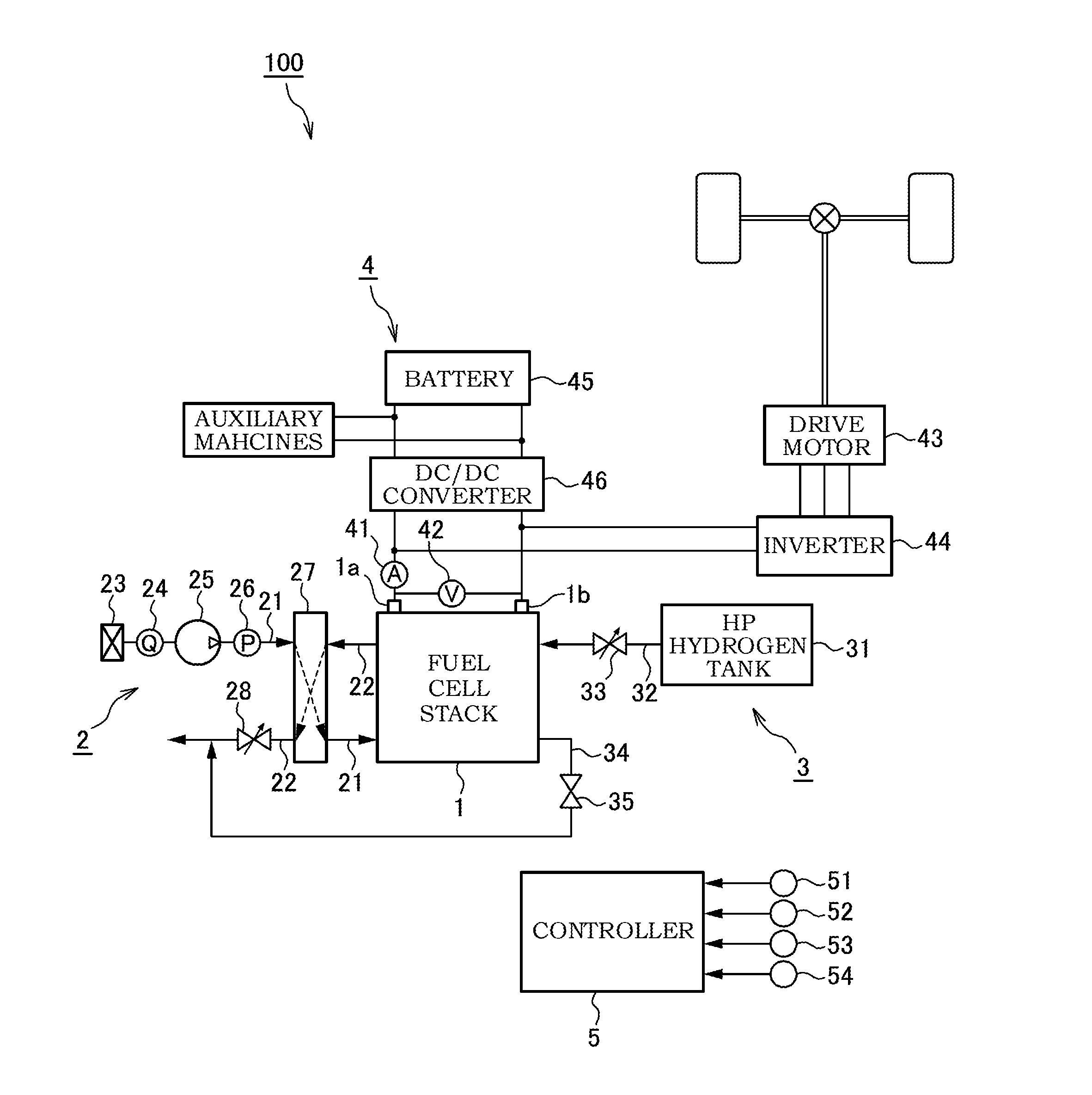
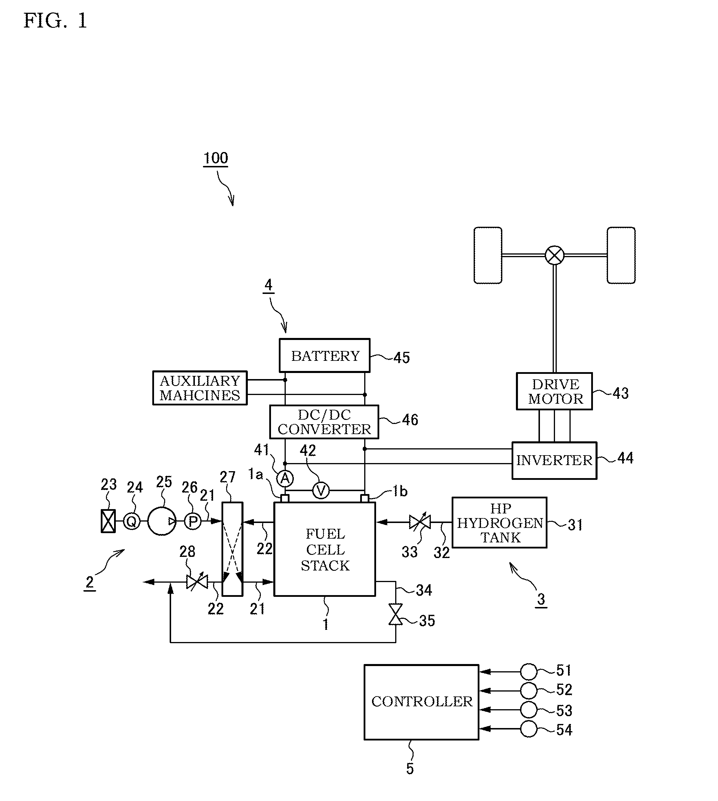
The present invention provides a fuel cell system that can suppress deterioration of its IV characteristic during a warm-up operation and acceleration request. This is achieved by controlling the pressure of the cathode gas to be supplied to the fuel cell by adjusting the cathode compressor so that its electricity consumption becomes larger than normal operation. This results in an increased generated electric power of the fuel cell during warm-up, leading to quicker heating up of the fuel cell.

Problems solved by technology

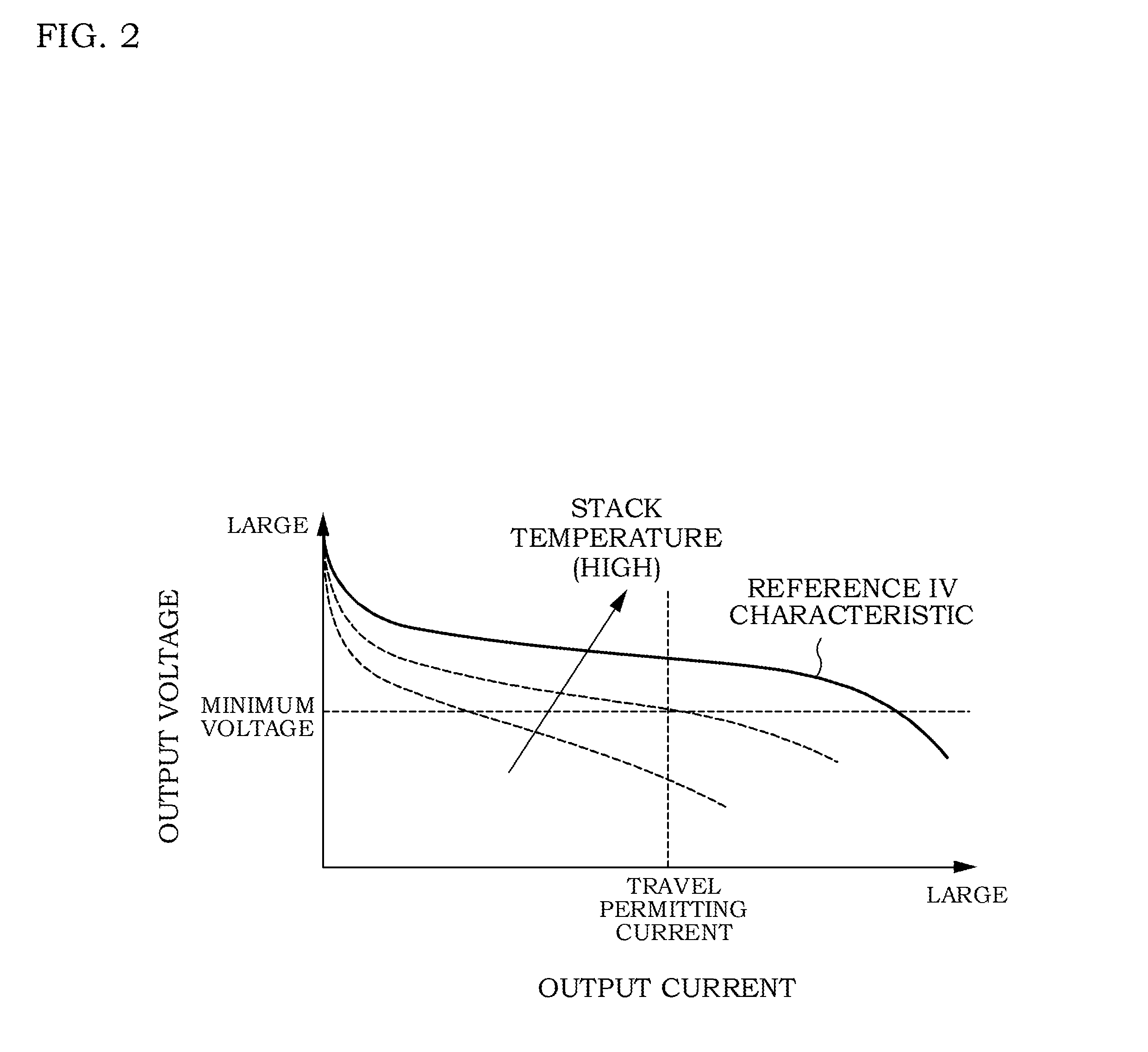
Further, the IV characteristic of the fuel cell deteriorates in the early period of the warm-up, and there is a possibility that an electric power necessary for traveling of the vehicle cannot be supplied.
For that reason, the generated electric power of the fuel cell is restricted compared with that during the normal operation.

Method used


Image

  • Fuel cell system
  • Fuel cell system
  • Fuel cell system

Examples


Embodiment Construction

[0018]Hereinafter, an embodiment of the present invention will be described with reference to the accompanying drawings and the like.

[0019]In a fuel cell, an electrolyte membrane is sandwiched between an anode electrode (fuel electrode) and a cathode electrode (oxidant electrode), and electric power is generated by supplying an anode gas (fuel gas) containing hydrogen to the anode electrode and supplying a cathode gas (oxidant gas) containing oxygen to the cathode electrode. Electrode reactions that proceed on both the anode electrode and the cathode electrode are as follows.

Anode Electrode: 2H2→4H++4e−  (1)

Cathode Electrode: 4H++4e−+O2→2H2O   (2)

[0020]The fuel cell generates an electromotive force of about one volt by means of these electrode reactions (1) and (2).

[0021]In a case where a fuel cell is utilized as a power source for a vehicle, the electric power to be required becomes greater. For this reason, the fuel cells are used as a fuel cell stack in which several hundreds of ...


PUM


Abstract

There is provided a fuel cell system that generates an electric power by supplying an anode gas and a cathode gas to a fuel cell. The fuel cell system includes: auxiliary machines and a drive motor driven by the generated electric power of the fuel cell; a pressure control unit configured to control a pressure of the cathode gas to be supplied to the fuel cell at a normal target pressure, the normal target pressure being used for ensuring an oxygen partial pressure within the fuel cell in accordance with the generated electric power of the fuel cell; and a warming-up pressure control unit configured to control the pressure of the cathode gas to be supplied to the fuel cell to become a predetermined warm-up acceleration target pressure during warm-up of the fuel cell, the predetermined warm-up acceleration target pressure being higher than the normal target pressure. In a case where there is a request to drive the drive motor during the warm-up of the fuel cell, the warming-up pressure control unit controls the pressure of the cathode gas to be supplied to the fuel cell to a warm-up target pressure between the normal target pressure and the warm-up acceleration target pressure.

Description

TECHNICAL FIELD[0001]The present invention relates to a fuel cell system.BACKGROUND ART[0002]As a conventional fuel cell system, there is one in which an IV characteristic (a current and voltage characteristic) of a fuel cell is estimated on the basis of an output voltage detected while changing an output current of the fuel cell (see JP2000-357526A).SUMMARY OF THE INVENTION[0003]In a fuel cell system under development now, during a normal operation after warm-up of a fuel cell, a pressure of a cathode gas to be supplied to the fuel cell is set up on the basis of an electric power required to cause a vehicle to travel so that an oxygen partial pressure necessary for generating the required electric power can be ensured, and a cathode compressor is driven in accordance with the pressure of the cathode gas thus set up.[0004]On the other hand, during the warm-up of the fuel cell, a pressure of a cathode side within the fuel cell is set up to a pressure for warming-up, which is higher t...

Claims


Application Information

Patent Timeline
IPC IPC(8): H01M8/04225H01M8/04746B60L11/18H01M8/04537H01M8/0438H01M8/04089H01M8/04302
CPCH01M8/04619H01M8/04302H01M2008/1095H01M2250/20Y02E60/50Y02T90/32H01M8/04104B60L11/1892B60L11/1885H01M8/1007H01M8/04225H01M8/04604H01M8/04395H01M8/1004H01M8/04268H01M8/04529H01M8/04589H01M8/04753B60L58/31B60L58/33H01M8/2457Y02T90/40
Inventor HOSHI, KIYOSHI
Owner NISSAN MOTOR CO LTD
Learn More