Cooling apparatus

Inactive Publication Date: 2009-03-12
HOSHIZAKI ELECTRIC CO LTD
View PDF3 Cites 14 Cited by
  • Summary
  • Abstract
  • Description
  • Claims
  • Application Information

AI Technical Summary

Benefits of technology

[0013]Even when the ambient temperature changes, the cooling apparatus according to the present invention can suppress the

Problems solved by technology

That is, in the cooling circuit 11, when a pressure on the high pressure side falls to nullify a difference between the pressure on the high pressure side and the pressure on the low pressure side from the outlet side of the expansion valve EV to the inlet side of the compressor CM, cooling of a target object by the evaporator EP cannot be controlled well, excessively cooling the target object.
The remote condenser type cooling apparatus 10 lacks the stability of the cooling function with respect to a change in outside temperature.
As the amount of the coolant to be filled in the cooling circuit 11 increases, a lot of the coolant sleeps in the compressor CM when the compressor CM is stopped, so that when the compressor CM is activated, the oil is likely to be discharged by oil foaming or the like, and the viscosity of the lubricant to be filled in the compressor CM drops, causing wearing or the like of the operat

Method used


Image

  • Cooling apparatus
  • Cooling apparatus
  • Cooling apparatus

Examples


embodiment

Operation of Embodiment

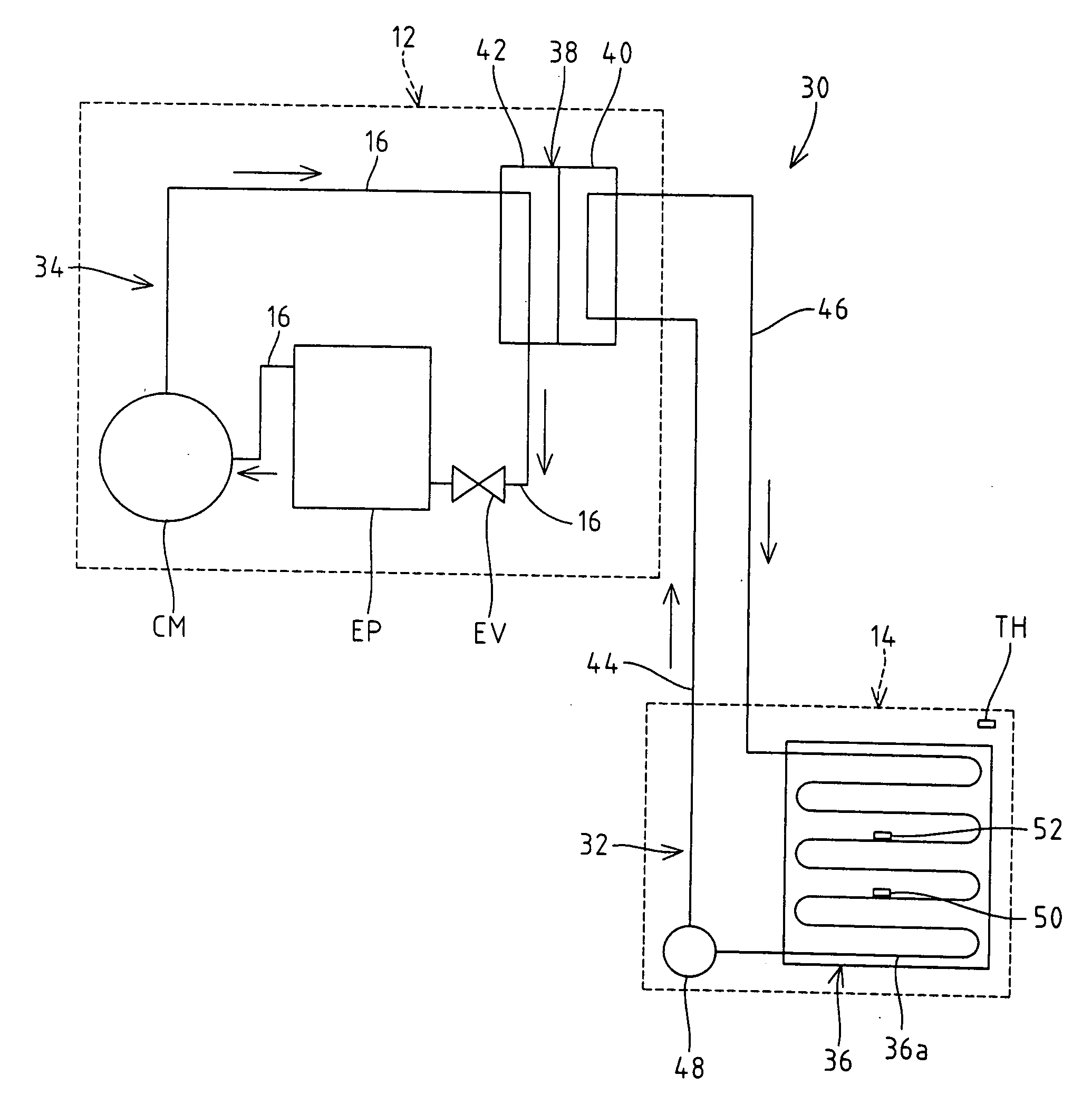
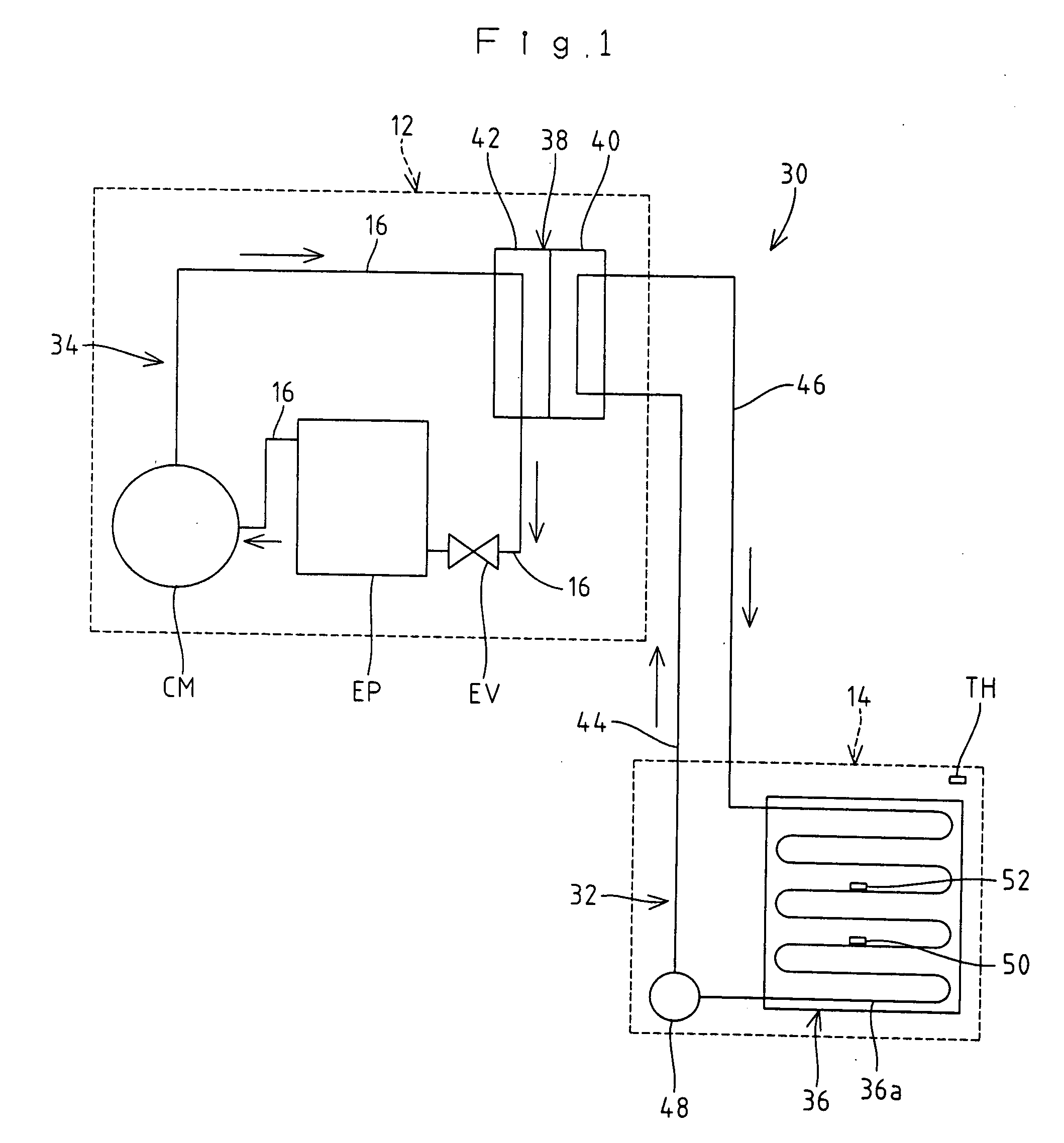
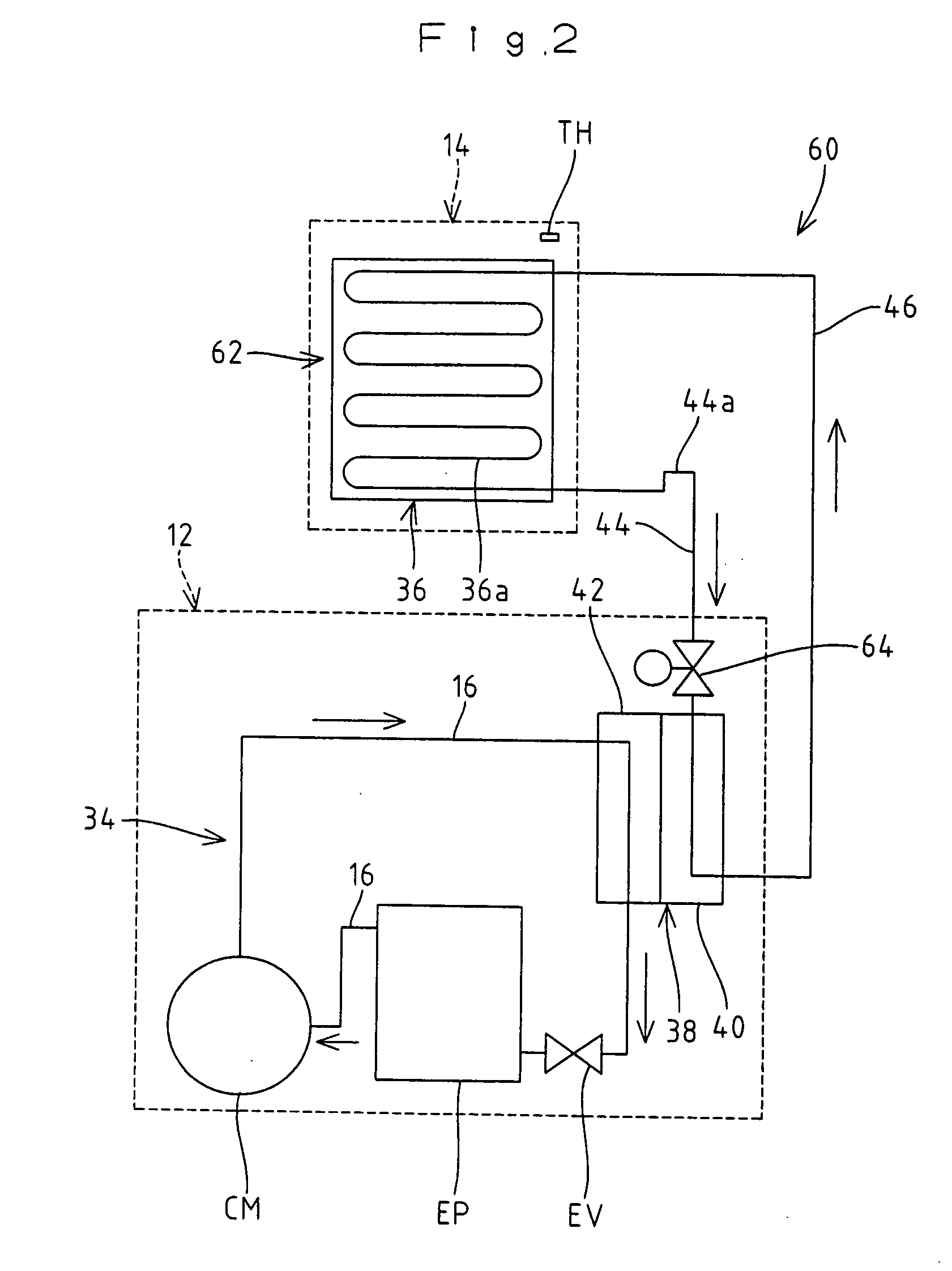
[0029]The operation of the cooling apparatus 30 according to the embodiment will be described next. In the primary circuit 32 of the cooling apparatus 30, a gas-phase primary coolant discharges heat to be liquefied while flowing through the heat discharge duct 36a of the condenser 36 to have phase transition from a gas-phase primary coolant to a liquid-phase primary coolant. The liquid-phase primary coolant is pumped out from the pump 48, flows into the first heat exchanging section 40 through the liquid piping 44, is vaporized by heat exchange with the gas-phase secondary coolant flowing through the second heat exchanging section 42 to have phase transition from a liquid-phase primary coolant to a gas-phase primary coolant. Then, the gas-phase primary coolant flows into the condenser 36 through the gas piping 46. In this manner, the circulation cycle of the primary coolant between the condenser 36 and the first heat exchanging section 40 is repeated.

[0030]Mea...


PUM


Abstract

A cooling apparatus which stably cools a target. The cooling apparatus includes a primary circuit that has a first heat exchanging section which is provided at a heat exchanger, and vaporizes a liquid-phase primary coolant to be a gas-phase primary coolant, and a condenser which condenses the gas-phase primary coolant to be the liquid-phase primary coolant, and lets the liquid-phase primary coolant flow to the first heat exchanging section from the condenser through a liquid piping and lets the gas-phase primary coolant flow to the condenser from the first heat exchanging section through a gas piping. The cooling apparatus further includes a secondary circuit having a second heat exchanging section, an expansion valve, an evaporator, and a compressor connected together by a coolant piping.

Description

BACKGROUND OF THE INVENTION[0001]1. Field of the Invention[0002]The present invention relates to a cooling apparatus for use in a refrigerator, a freezer, an ice making machine, an air-conditioning system and the like.[0003]2. Description of the Related Art[0004]As a cooling apparatus for use in a refrigerator, a freezer, an ice making machine, an air-conditioning system and the like, a so-called remote condenser type (also called separate type) cooling apparatus 10 having a compressor CM and an evaporator EP disposed in a main body unit 12 arranged indoor and having a condenser CD disposed in an external unit 14 arranged outdoor has been proposed (see, for example, Japanese Patent Application Laid-Open No. H8-200746), as shown in FIG. 6. The cooling apparatus 10 of this type has a disadvantage that the provision of the condenser CD which is a heat discharging part outdoor can suppress a temperature rise in the main body unit 12.SUMMARY OF THE INVENTION[0005]In an environment where ...

Claims


Application Information

Patent Timeline
IPC IPC(8): F25B1/00F25B49/00
CPCF25B49/027F25B2400/06F25B2339/047
Inventor KAGA, SHINICHIHIRANO, AKIHIKOSEKI, KAZUYOSHI
Owner HOSHIZAKI ELECTRIC CO LTD
Why Eureka
Try Eureka