Liquid jetting device

A technology of jetting device and liquid jetting head, which is applied in the direction of measuring device, sampling, printing, etc., and can solve problems such as hindering ink jetting

Inactive Publication Date: 2006-05-10
SEIKO EPSON CORP
View PDF1 Cites 17 Cited by
  • Summary
  • Abstract
  • Description
  • Claims
  • Application Information

AI Technical Summary

Problems solved by technology

This affects to some extent the meniscus of the ink generated in the nozzle,

Method used


Image

  • Liquid jetting device
  • Liquid jetting device
  • Liquid jetting device

Examples


Example

[0040] (First embodiment)

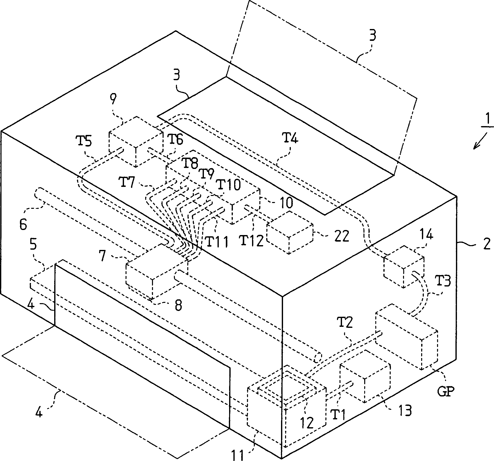
[0041] The following will refer to figure 1 Turning to FIG. 4, the first embodiment of the present invention will be described.

[0042] Such as figure 1 As shown, the printer 1 used as a liquid ejecting device includes a substantially parallelepiped frame 2. The paper feeding tray 3 is formed on the upper surface of the frame 2, and the paper output tray 4 is provided on the front surface of the frame 2. Each of the paper feeding tray 3 and the paper output tray 4 is configured to be accommodated in the frame 2 in a state of being folded with a hinge mechanism not shown.

[0043] The platen 5 extends longitudinally in the frame 2. The recording paper is inserted into the frame 2 via the paper feeding tray 3, and is supplied to the platen 5 by a paper feeding mechanism not shown. Then, the recording paper is conveyed from the frame 2 to the outside via the paper discharge tray 4.

[0044] The guide member 6 is provided in the frame 2 and extends in pa...

Example

[0070] (Second embodiment)

[0071] The following will refer to Figure 5 with Figure 6 The second embodiment of the present invention is described.

[0072] In the second embodiment, similar to the check valve 14 of the first embodiment, the check valve suppresses the backflow of waste ink and air to the cap member 12. In terms of the installation position relative to the frame 2 of the printer 1, the check valve of the second embodiment is different from the check valve 14 of the first embodiment. Thus, the configuration of the check valve of the second embodiment is modified accordingly. Therefore, the following description focuses on the difference between the first embodiment and the second embodiment. The same or similar reference numerals are used to indicate the parts of the second embodiment that are the same or similar to the corresponding parts of the first embodiment.

[0073] Such as Figure 5 As shown, the gear pump GP is connected to the cover member 50 through a c...


PUM


Abstract

To clean the recording head, the printer seals the nozzles with a cap member, thus forming a closed circulation system. In this state, the gear pump is activated to suck waste liquid and air from the cover member. Then, waste ink and air are introduced into the first ink tank by sequentially flowing in the cap member, the check valve, the tube, the gear pump, and a different tube. Air is introduced into the second ink tank as pressurized air through a corresponding tube. A check valve prevents waste ink and pressurized air from returning to the cover assembly. This suppresses backflow of liquid and air, and ink ejection is efficiently performed.

Description

technical field [0001] The present invention relates to liquid ejection devices. Background technique [0002] Conventionally, an inkjet recording device is collectively referred to as a type of liquid ejection device. Inkjet recording devices include "off-carriage" types in which an ink holder is connected to a recording head via an ink supply tube. The ink holder is provided in an ink tank as an ink container. The ink holder is pressurized with pressurized air introduced into the ink cartridge, for example by a pump. This causes the ink in the ink holder to be sent to the recording head through the ink supply tube, so that the recording head is supplied with ink. Then, the ink is ejected from the nozzles of the recording head toward the recording paper as ink droplets for recording characters or images. [0003] Typically, when it is necessary to prevent ink ejection problems, the inkjet recording apparatus performs cleaning that discharges air bubbles or ink with incr...

Claims


Application Information

Patent Timeline
IPC IPC(8): B41J2/18G01N1/00G01N35/10
Inventor 岩崎充孝
Owner SEIKO EPSON CORP
Why Eureka
Try Eureka