High-frequency signal amplifier circuit, power amplifier module, front-end circuit, and communication apparatus

a technology of high-frequency signal and amplifier circuit, which is applied in the direction of amplifiers, amplifiers with semiconductor devices/discharge tubes, amplifiers, etc., can solve the problems of reducing saturation output or power added efficiency, suppressing the operation range of high-frequency signal amplifier transistors, etc., to maintain amplification performance, reduce the noise level of the reception band during transmission time, and reduce the noise level of the reception band

Active Publication Date: 2017-10-03
MURATA MFG CO LTD
View PDF3 Cites 16 Cited by
  • Summary
  • Abstract
  • Description
  • Claims
  • Application Information

AI Technical Summary

Benefits of technology

[0026]With the above configuration, a communication apparatus in which a reception band noise level during the transmission time is lowered while maintaining the amplification performance for high-frequency transmission signals can be provided.
[0027]With the high-frequency signal amplifier circuit according to the embodiments of the present disclosure, it is possible to lower a reception band noise level during the transmission time while maintaining the amplification performance for high-frequency transmission signals.

Problems solved by technology

However, in this case, when a DC bias current is supplied from the bias circuit, a voltage applied to the base of the high-frequency signal amplifier transistor is dropped due to the stated resistor, thereby raising a problem that an operating range of the high-frequency signal amplifier transistor is suppressed and another problem that saturation output or power added efficiency is lowered.

Method used


Image

  • High-frequency signal amplifier circuit, power amplifier module, front-end circuit, and communication apparatus
  • High-frequency signal amplifier circuit, power amplifier module, front-end circuit, and communication apparatus
  • High-frequency signal amplifier circuit, power amplifier module, front-end circuit, and communication apparatus

Examples


first embodiment

1.1 Configuration of Communication Apparatus

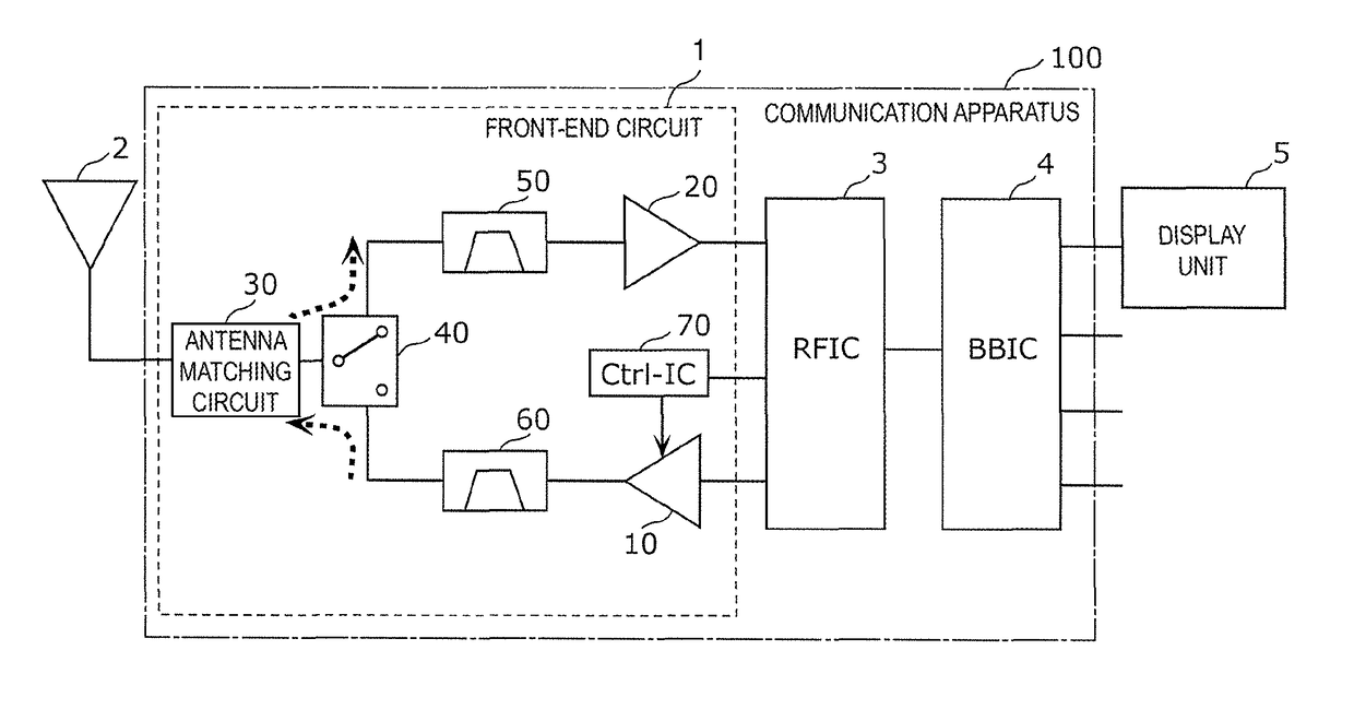
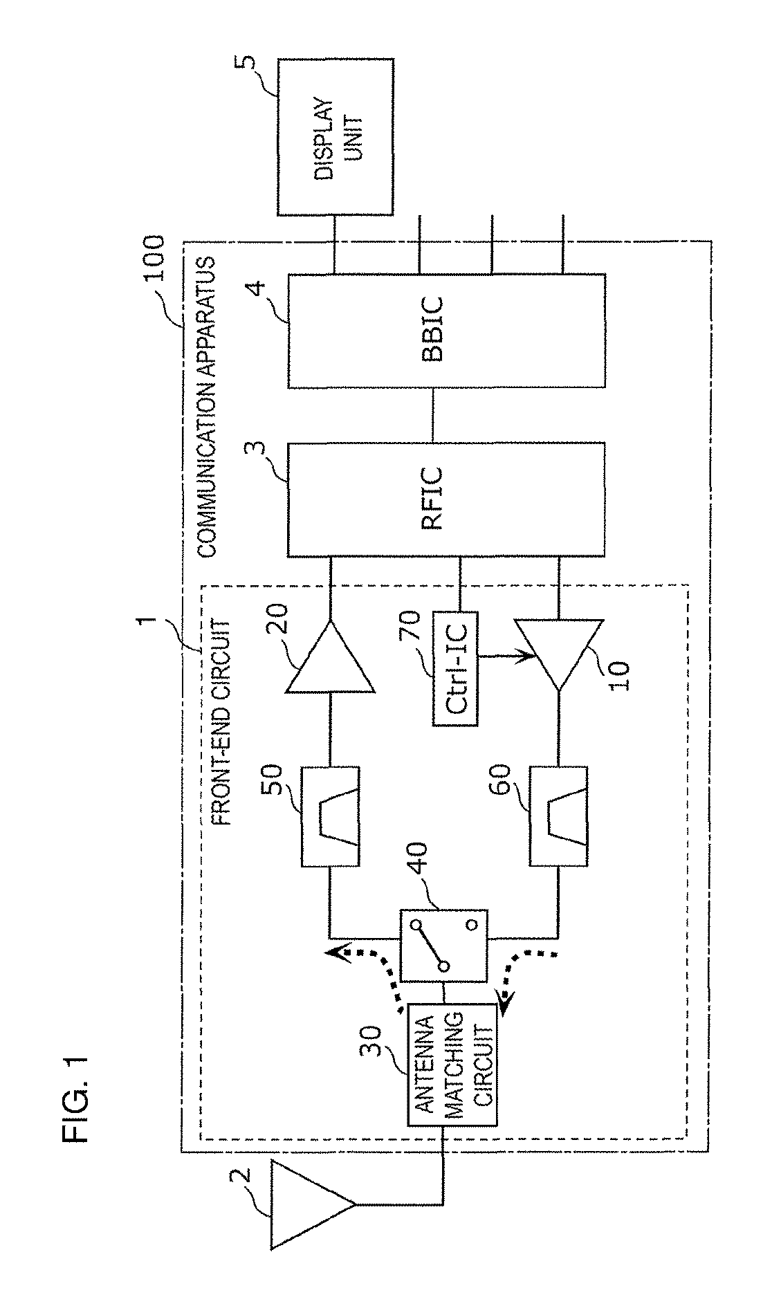
[0038]FIG. 1 is a functional block configuration diagram of a communication apparatus 100 according to a first embodiment. In FIG. 1, the communication apparatus 100, an antenna device 2, and a display unit 5 are illustrated. The communication apparatus 100 includes a front end circuit 1, an RF signal processing circuit (RFIC) 3, and a baseband signal processing circuit (BBIC) 4. The front-end circuit 1 is disposed, for example, in a front-end section of a cellular phone supporting multimode / multiband use.

[0039]The front-end circuit 1 includes a PA (Power Amplifier) module 10, a low noise amplifier circuit 20, an antenna matching circuit 30, an antenna switch 40, a reception filter 50, a transmission filter 60, and a control IC 70.

[0040]The antenna matching circuit 30 is a circuit that is connected to the antenna device 2 and the antenna switch 40, and achieves matching between the antenna device 2 and the front-end circuit 1. This makes i...

second embodiment

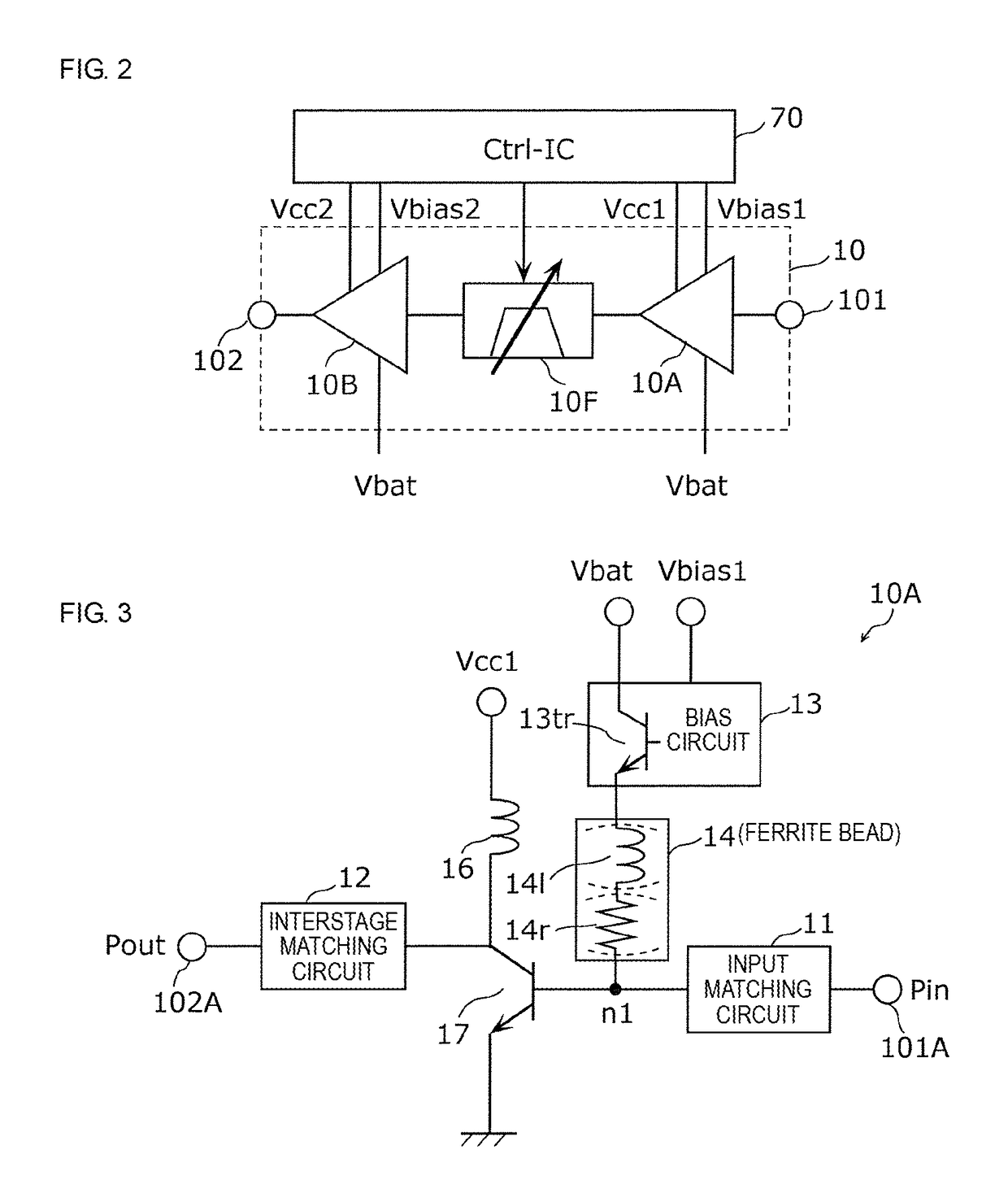
[0090]In a second embodiment, described is a configuration in which an arrangement relationship among the preceding amplifier device 10A configured of the high-frequency signal amplifier circuit according to the first embodiment, the subsequent amplifier device 10B, and the variable filter circuit 10F is optimized.

[0091]In the case where each of the preceding amplifier device 10A, the subsequent amplifier device 10B, the variable filter circuit 10F, and the control IC 70 is configured of a different chip, the resultant circuit configuration cannot contribute to the miniaturization of the front-end circuit 1. Meanwhile, in the case where the preceding amplifier device 10A and the subsequent amplifier device 10B are integrated in the same chip in order to realize the miniaturization, there arises a risk that the quality of a transmission signal is deteriorated due to oscillation or the like generated by strengthened mutual interference between the high-frequency signals.

[0092]FIG. 6A ...


PUM


Abstract

A high-frequency signal amplifier circuit is used in a front-end circuit configured to propagate a high-frequency transmission signal and a high-frequency reception signal, and includes an amplifier transistor configured to amplify the high-frequency transmission signal; a bias circuit configured to supply a bias to a signal input end of the amplifier transistor; and a ferrite bead, one end of which is connected to a bias output end of the bias circuit and the other end of which is connected to the signal input end of the amplifier transistor, having characteristics in which impedance in a difference frequency band between the high-frequency transmission signal and the high-frequency reception signal is higher than impedance in DC.

Description

[0001]This application claims priority from Japanese Patent Application No. 2016-069734 filed on Mar. 30, 2016. The contents of this application are incorporated herein by reference in its entirety.BACKGROUND[0002]The present disclosure relates to high-frequency signal amplifier circuits, power amplifier modules, front-end circuits, and communication apparatuses.[0003]Nowadays, a cellular phone is required to support a plurality of frequency bands (multiband use) while the cellular phone being a single terminal. A front-end circuit that supports the multiband use is required to propagate transmission and reception signals corresponding to a plurality of frequency bands without necessarily the transmission and reception signals being deteriorated. As such, a high-frequency signal amplifier circuit for amplifying the transmission signal is required to lower a reception band noise level during a transmission time while maintaining high amplification performance.[0004]International Publ...

Claims


Application Information

Patent Timeline
Patent Type & Authority Patents(United States)
IPC IPC(8): H03F1/26H04B1/16H03F3/195H03F1/56H03F3/213
CPCH03F1/26H04B1/16H03F3/195H03F1/56H03F3/213H03F2200/165H03F2200/171H03F2200/451H03F2200/318H03F2200/222H03F2200/387H03F2200/555H03F1/0261H03F3/245H03F2200/246H03F2200/411H04B1/0458
Inventor OBIYA, HIDENORINAKAJIMA, REIJI
Owner MURATA MFG CO LTD
Why Eureka
Try Eureka