Battery module and method of manufacturing the same

a battery module and manufacturing method technology, applied in the field of batteries, can solve the problems of affecting so as to improve the assembling accuracy of batteries

Inactive Publication Date: 2011-09-29
PANASONIC CORP
View PDF5 Cites 16 Cited by
  • Summary
  • Abstract
  • Description
  • Claims
  • Application Information

AI Technical Summary

Benefits of technology

The present invention has been devised to solve the problems of the related art. An object of the present invention is to improve the assembling accuracy of a battery module while suppressing a voltage drop of lead plates, the battery module containing series-connected parallel blocks that are connected to a protection circuit via the lead plates, the parallel block containing parallel-connected cells.

Problems solved by technology

In a method of manufacturing a battery module according to the related art, however, lead plates bent into U shapes may cause the following problem: upon discharging to audio-visual apparatuses such as a PC, a current passes through the lead plates from the battery module and a voltage drop may occur on the lead plates because of a specific resistance to the metal of the lead plates.
In the case where the lead plates are bent into U shapes in the manufacturing process, the bending step is added, the assembling accuracy is likely to vary after the formation of the battery module, and the bent parts protrude out of the outside shape of the battery module more than in the specifications, which does not allow size reduction.
Further, it becomes difficult or impossible to package the battery module.

Method used


Image

  • Battery module and method of manufacturing the same
  • Battery module and method of manufacturing the same
  • Battery module and method of manufacturing the same

Examples


first embodiment

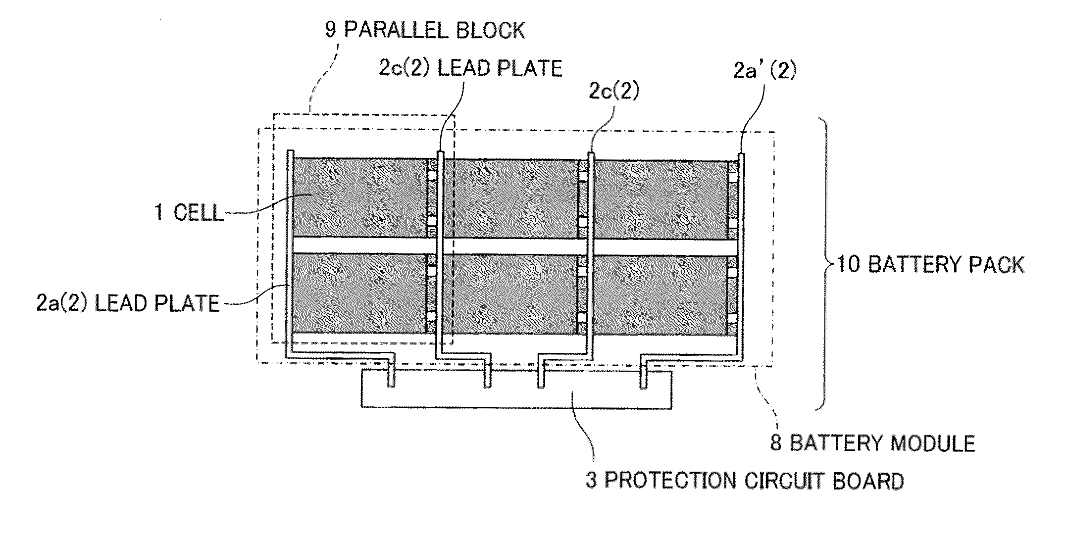
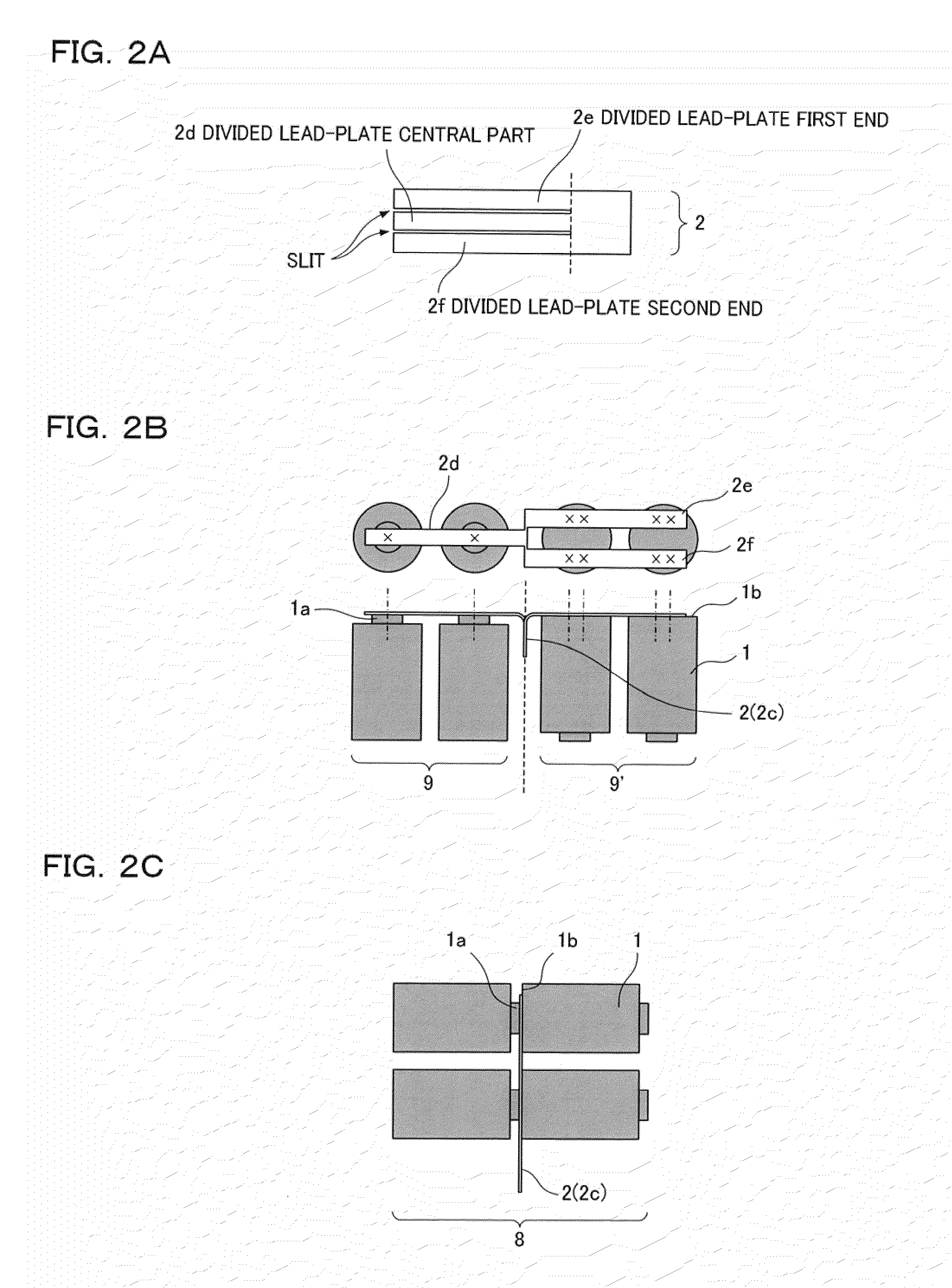
FIGS. 2A, 2B, and 2C are explanatory drawings showing the structure of a battery module according to a first embodiment.

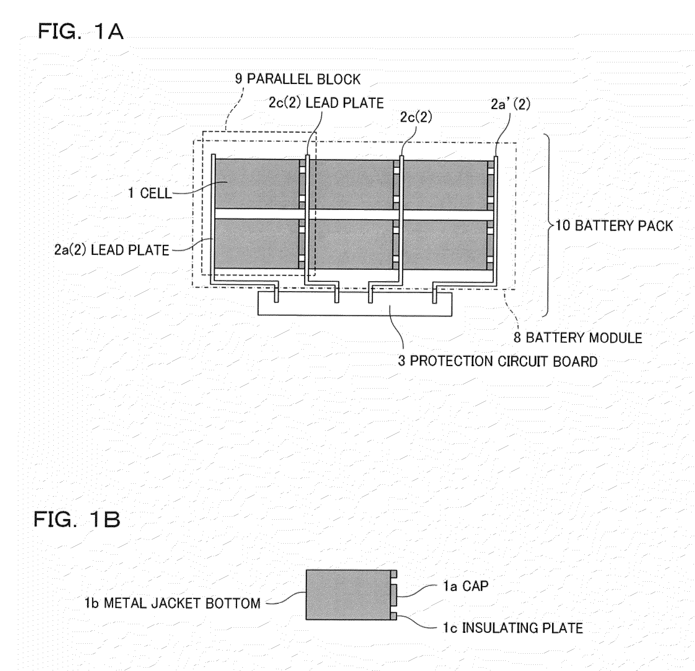
As shown in FIG. 2A, one side of a lead plate 2 of the first embodiment is divided into three by slits and is connected to cells. The lead plate 2 has a divided lead-plate central part 2d, a divided lead-plate first end 2e, and a divided lead-plate second end 2f. The divided lead-plate central part 2d connects one surface of the lead plate to caps 1a serving as the positive electrodes of cells 1. The divided lead-plate first end 2e and the divided lead-plate second end 2f connect the other surface of the lead plate to metal jacket bottoms 1b serving as the negative electrodes of the cells 1.

Typically, the metal jacket of the cell 1 is cylindrically formed by a drawing and ironing (DI) process in which a metal coil material is drawn into a cup and the side wall is stretched by ironing in several steps to form the cylindrical body.

The lead plate 2 is a metal plate. T...

second embodiment

FIGS. 3A, 3B, and 3C are explanatory drawings showing a method of manufacturing a battery module according to a second embodiment. FIG. 3A shows a setting tool used for manufacturing the battery module. FIG. 3B shows a pressing state of a pressing tool. FIG. 3C shows radiation beams during melting.

As in the first embodiment, a lead plate 2 used in the second embodiment has one side divided into three by slits and connected to cells 1. The lead plate 2 is made up of a divided lead-plate central part 2d, a divided lead-plate first end 2e, and a divided lead-plate second end 2f.

In a method of connecting the lead plate 2 and the cells 1, as shown in FIG. 3A, the cells 1 and the lead plate 2 are set on a lower setting tool 5a of a setting tool 5. The lower setting tool 5a has recessed parts of predetermined dimensions to position the cells 1 and the lead plate 2, so that the cells 1 and the lead plate 2 are set at predetermined positions.

The divided lead-plate central part 2d is tempora...

third embodiment

In the related art, the positive and negative electrodes of parallel blocks to be connected in series are hard to weld and connect on both sides of a single flat lead plate. In the foregoing embodiments, the lead plate is divided into parts to be connected to the positive electrodes and the negative electrodes, the parallel blocks are welded to the parts in an opened state, and the parts are returned to the shape of the single lead plate. Hence, without bending the lead plate into U shape, the cells are connected in parallel to form the parallel blocks and the parallel blocks are connected in series to fabricate the battery module.

A feature of the present embodiment is that a lead plate is bent to form projecting portions beforehand thereon, so that a clearance allowing laser radiation is formed between parallel blocks connected in series. With this configuration, the positive electrodes and the negative electrodes of the parallel blocks to be connected in series can be welded and c...


PUM

PropertyMeasurementUnit
thicknessaaaaaaaaaa
thicknessaaaaaaaaaa
widthaaaaaaaaaa

Abstract

A battery module 8 containing parallel blocks 9 connected to a protection circuit via a lead plate 2, wherein the parallel blocks 9 are welded to both sides of the lead plate without bending the lead plate 2 into a U shape. Thus it is possible to reduce the length of the lead plate 2 and suppress a voltage drop on the lead plate 2. Further, since the lead plate 2 is not bent into a U shape, the assembling accuracy of the battery module is improved and the battery module is easily packaged with a small size.

Description

FIELD OF THE INVENTIONThe present invention relates to a battery module and a method of manufacturing the same, the battery module containing series-connected parallel blocks, each containing parallel-connected cells.BACKGROUND OF THE INVENTIONIn recent years, in the field of audio-visual apparatuses typified by notebook computers, small lithium-ion batteries with high output power have been used. In order to obtain a predetermined output and a predetermined capacity for a notebook computer, a battery module is used that contains series-connected parallel blocks, each containing parallel-connected cells.The parallel blocks are connected in series via lead plates and the lead plates are connected to a protection circuit. The parallel blocks are hard to connect to both sides of the lead plate in view of welding. Thus in the related art, parallel blocks to be connected in series are welded to both ends of a surface of a lead plate and then the lead plate is bent, so that a space-saving...

Claims


Application Information

Patent Timeline
Patent Type & Authority Applications(United States)
IPC IPC(8): H01M2/26H01M10/42B23K26/20H01M50/528H01M50/503H01M50/509H01M50/516H01M50/519
CPCY10T29/49108H01M10/0587H01M10/425H01M10/052H01M2/204Y10T29/49826H01M2/022Y02E60/10H01M50/107Y02P70/50H01M50/519H01M50/516H01M50/509H01M50/503
Inventor UCHIDA, OSAMUIKURUMI, KAZUHIROKUMAZAWA, SEIJIFUNAMI, KOJIADACHI, MASAZUMI
Owner PANASONIC CORP
Why Eureka
Try Eureka