Automatic assembly equipment for spring lock

An automatic assembly and pin lock technology, applied in metal processing equipment, assembly machines, manufacturing tools, etc., can solve the problems of high error rate, low assembly efficiency and assembly accuracy, and low assembly accuracy

Active Publication Date: 2011-11-23
JINHUA KETE PRECISION MACHINERY
View PDF6 Cites 27 Cited by
  • Summary
  • Abstract
  • Description
  • Claims
  • Application Information

AI Technical Summary

Problems solved by technology

The depth of the key teeth of the existing pin lock is recognized by the workers' eyes during the pin lock assembly, and the ass

Method used


Image

  • Automatic assembly equipment for spring lock
  • Automatic assembly equipment for spring lock
  • Automatic assembly equipment for spring lock

Examples


Example Embodiment

[0036] Example 1

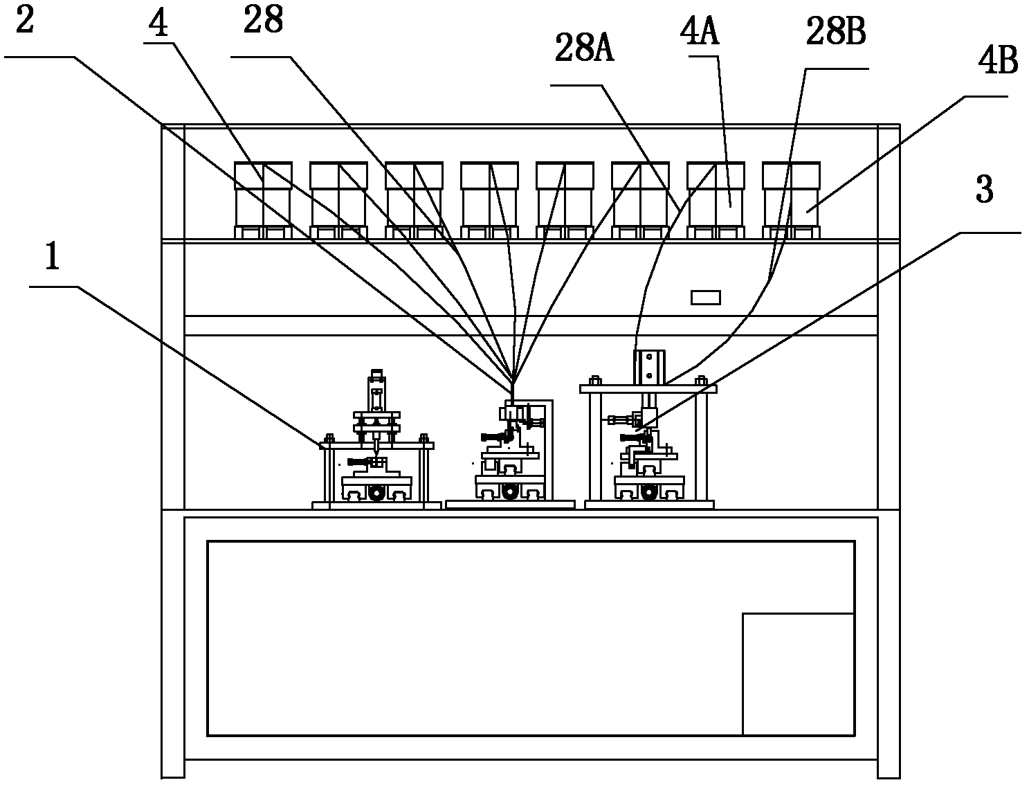
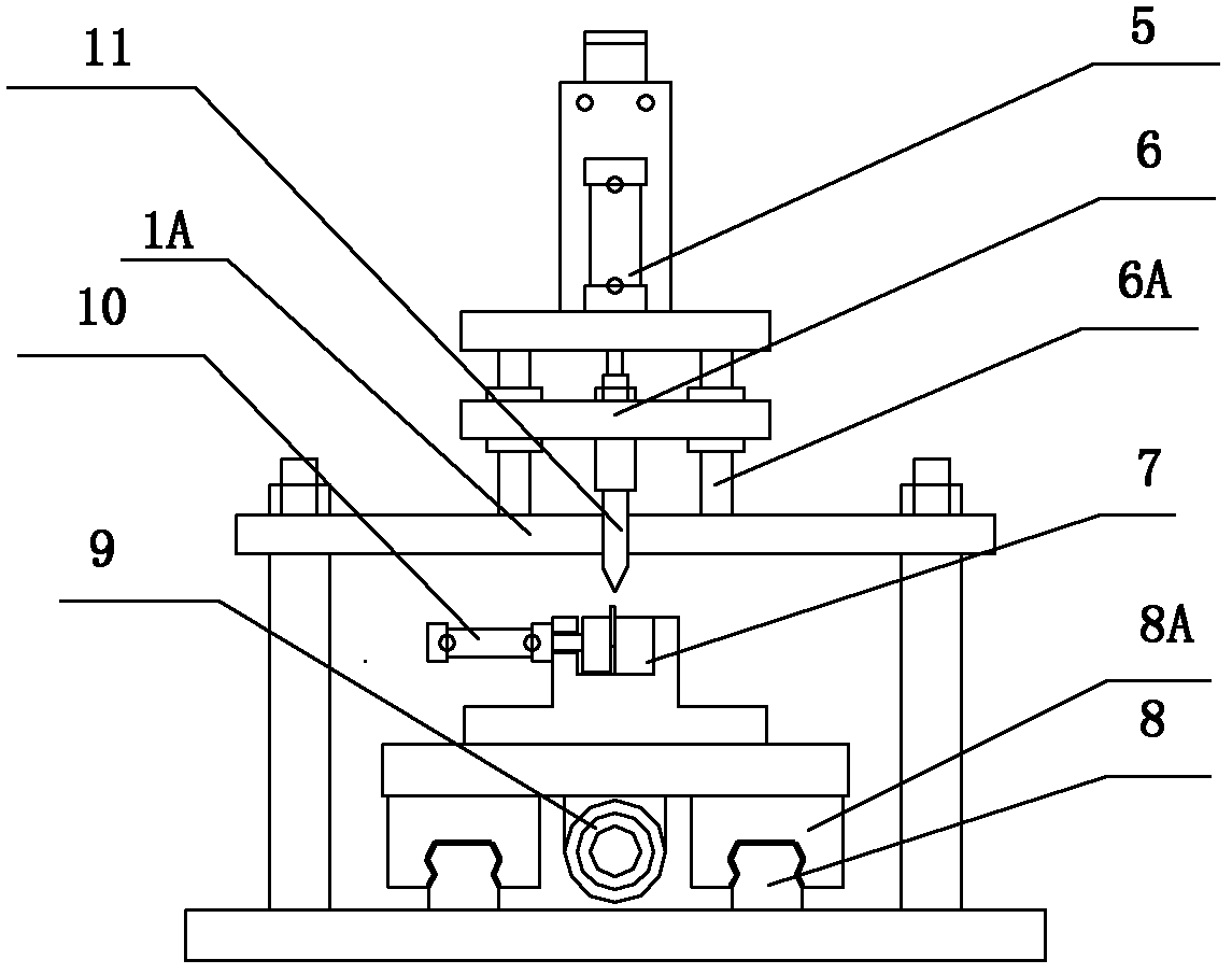
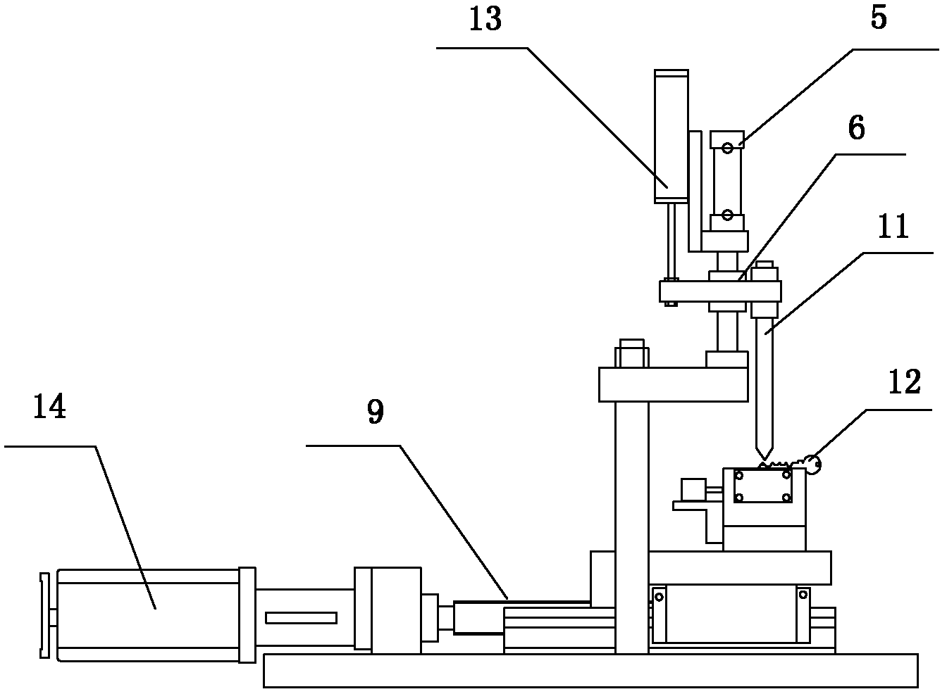
[0037] like Figure 1-12 The shown automatic assembling equipment for marble locks includes a rack, a pneumatic control assembly and a microcomputer controller. The rack is provided with a marble feeding tray 4, a spring feeding tray 4A, a sealing bullet feeding tray 4B, and a key tooth flower identification device. 1. The marble pendulum device 2 and the spring sealing device 3, the key tooth flower identification device 1, the marble pendulum device 2 and the spring sealing device 3 are respectively connected with the microcomputer controller, and the marble feeding plate 4 is connected with the marble pendulum device. 2 are connected, both the spring feeding tray 4A and the sealing bullet feeding tray 4B are connected with the spring sealing bullet installation device 3, the microcomputer controller controls the pneumatic control assembly, the key tooth flower identification device 1, the bullet swinging device 2 and the spring sealing bullet installation...

Example Embodiment

[0052] Example 2

[0053] The marble lock of the double lock cylinder has two rows of marbles in the front and the rear, such as the double unlocking cylinder of the door lock. In the production and processing process of the double-cylinder marble lock, various reasons can cause the margins on both sides of the lock body to be unequal, and the error is still very random.

[0054] like figure 1 , figure 2 , image 3 , Figure 8 , Figure 9 , Figure 10 , Figure 11 , Figure 12 , Figure 13 , Figure 14 , Figure 15 and Figure 16 The shown automatic assembling equipment for the pinball lock is mainly suitable for pinball locks with double lock cylinders. The other structures are the same as those in the first embodiment.

[0055] like Figure 13 and Figure 14 The shown pinball pendulum device 2 includes all the structures of Embodiment 1, and the pinball pendulum device 2 also includes the second moving assembly 24 of the lock body, the second moving assembly c...

Example Embodiment

[0059] Example 3

[0060] like figure 1 , figure 2 , image 3 , Figure 17 , Figure 18 , Image 6 , Figure 7 , Figure 8 , Figure 9 , Figure 10 , Figure 11 and Figure 12 The shown automatic assembling equipment for a pinball lock is the same as that of the first embodiment in other structures, and the pinball swinging device 2 is different from that in the first embodiment, and is also mainly suitable for a pinball lock with double lock cylinders.

[0061] The ball swinging device 2 also includes a second moving assembly 24 of the lock body, a second moving assembly cylinder 30, an intermediate positioning block 22, a front positioning block 29 and a rear positioning block 23. The second moving assembly 24 of the lock body is fixed on the lock body fixture to move. In terms of mechanism, the lock body clamp 18 is fixed on the second moving assembly 24 of the lock body, the cylinder 30 of the second moving assembly is connected to the second moving assembly 24...


PUM


Abstract

The invention relates to assembly equipment for lockset, in particular to automatic assembly equipment for a spring lock. The automatic assembly equipment comprises a machine frame and a microcomputer controller, wherein a spring feed disc, a mechanical spring feed disc, a spring sealing feed disc, a key bit identification device, a spring swinging device and a mechanical spring sealing installation device are arranged on the machine frame, wherein the key bit identification device, the spring swinging device and the mechanical spring sealing installation device are connected with the microcomputer controller respectively; the spring feed disc is connected with the spring swinging device; and the mechanical spring feed disc and the spring sealing feed disc are connected with the mechanical spring sealing installation device. The automatic assembly equipment for the spring lock has the advantages of novel structure, high automaticity and high assembly efficiency and assembly accuracy.

Description

technical field [0001] The invention relates to a lock assembly device. Background technique [0002] Pin locks are a common lock, such as door locks, padlocks, etc. need to use pin locks, pin locks have the difference between single-sided pinholes and multilateral pinholes (mainly pinholes on both sides), such as Figure 12 As shown, it is a door lock type pin lock with pin holes on both sides. The principle of the pin lock is to use a plurality of cylindrical parts of different heights, that is, pin pins 102 to lock the lock cylinder, insert a key 103, and various pin pins 102 are pushed to the same height. , the lock cylinder is released. In the assembly and production process of the pin lock, the height of the key tooth must be determined first, and the corresponding suitable pin 102 should be selected according to the height of the key pin, that is, the height of the pin 102 and the position of the pin 102 should be selected. This process in production is called pendulu...

Claims


Application Information

Patent Timeline
IPC IPC(8): B23P21/00
Inventor 黄安伟黄加卫
Owner JINHUA KETE PRECISION MACHINERY
Why Eureka
Try Eureka