Efficient and high-precise robot automatic milling system in digital assembly process of airplane

An automatic milling and robot technology, applied in the direction of manipulators, positioning devices, maintenance and safety accessories, etc., can solve the problems of uneven allowance, difficult repair, low work efficiency, etc., and achieve reduced labor intensity, high reliability, and improved assembly The effect of precision

Active Publication Date: 2017-10-17
上海昂恒航空自动化装备有限公司
View PDF8 Cites 27 Cited by
  • Summary
  • Abstract
  • Description
  • Claims
  • Application Information

AI Technical Summary

Problems solved by technology

[0003] The purpose of the present invention is to solve the defects of the prior art, and provide an efficient and high-precision robot automatic milling system in the digital assembly of aircraft, which adopts a digital method and a brand-new milling process to realize the automatic milling function of the robot, inst

Method used


Image

  • Efficient and high-precise robot automatic milling system in digital assembly process of airplane
  • Efficient and high-precise robot automatic milling system in digital assembly process of airplane
  • Efficient and high-precise robot automatic milling system in digital assembly process of airplane

Examples


Example Embodiment

[0044] Example 1

[0045] The specific processing process of large aircraft parts is as follows:

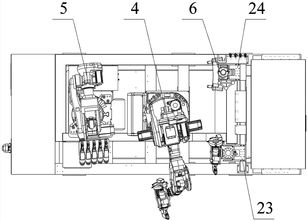
[0046] Step 1: The laser tracker scans the feature points of the front and middle fuselages to be assembled, establishes a global coordinate system, and transmits this global coordinate system information to the measurement system 6 through an interface;

[0047] Step 2: The measurement system 6 is placed on the measurement system quick-change bracket 24, the coordinate tracking system 61 tracks the scan head of the scanning system 62 in real time, and places 4 to 4 on the AGV trolley 1 5 target balls are ready for posture correction;

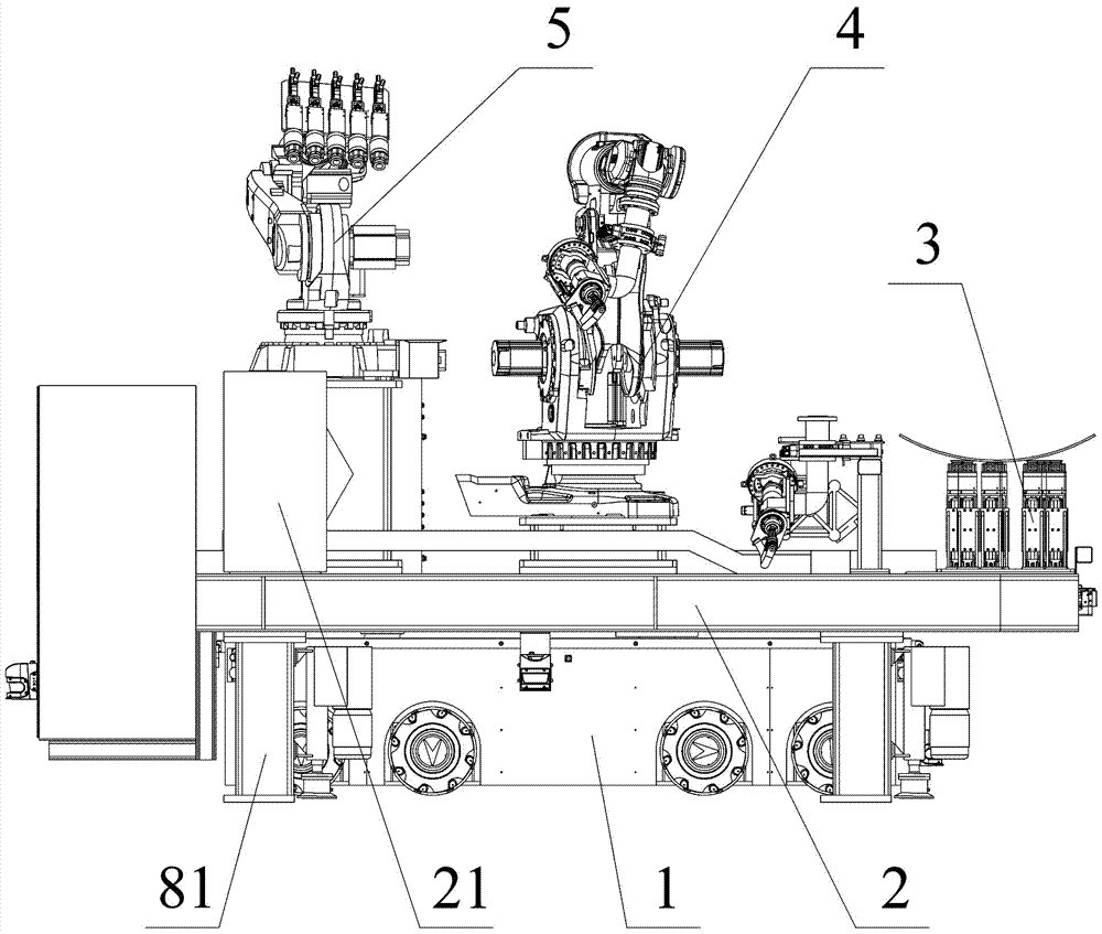
[0048] Step 3: Control the AGV trolley 1 to enter the first station of the processing area (the processing robot 42 enters first, and the center of the processing robot base 41 is consistent with the central axis of the machine head to be processed) and anchored;

[0049] Step 4: The processing robot 42 assembles the measurement system 6, and the scanning ...

Example Embodiment

[0064] Example 2

[0065] The specific processing process of aircraft small parts is as follows:

[0066] Step 1: Determine the layout of the vacuum chuck 74 according to the projection range of the flap onto the flexible positioning tooling system 3. After fixing each vacuum chuck 74, determine the horizontal coordinate of each vacuum chuck 74 relative to the tooling reference point with a measuring ruler ;

[0067] Step 2: Import the theoretical digital model of the flap into the GeoMagic software for simulation calculation. According to the theoretical digital model of the flap and the distribution of each vacuum chuck 74 relative to the fixture reference point, calculate each vacuum chuck in the flexible positioning tooling system 3 74 telescopic height;

[0068] Step 3: Adjust the height of each vacuum suction cup 74;

[0069] Step 4: Correlate the reference point of the flap with the reference point of the tooling and fix it on the flexible positioning tooling system 3;

[0070] ...


PUM


Abstract

The invention provides an efficient and high-precise robot automatic milling system in the digital assembly process of an airplane. The system is characterized in that the system comprises a robot off-line programming and simulation system, a robot automatic control system, an AGV, a working platform arranged on the AGV, a flexible positioning tool system arranged on the working platform, a machining system, an auxiliary clamping system and a measuring system; the machining system comprises a machining robot and a machining tail end actuator connected with the machining robot, and the auxiliary clamping system comprises an auxiliary clamping robot and an auxiliary clamping tail end actuator connected with the auxiliary clamping robot; and machining objects of the robot automatic milling system comprise airplane large parts and airplane small parts. According to the efficient and high-precise robot automatic milling system in the digital assembly process of the airplane, robot automatic milling is adopted to replace manual work to grind the assembly allowance of the airplane, the problems that in the assembly process, the allowance is uneven in grinding, difficult to repair, low in working efficiency and the like are solved, the assembly precision and efficiency of the airplane are promoted, the labor intensity of workers is relieved, and physical and psychological health of the workers are guaranteed.

Description

technical field [0001] The present invention relates to a robot automatic milling processing system, and in particular discloses a high-efficiency and high-precision robot automatic milling system in aircraft digital assembly, which is applied to various typical titanium alloy parts and composite materials in the digital assembly process of large-scale equipment in the aviation field. Automatic milling of aircraft wall panels, fuselage sections, flaps, doors and skin parts of laminated materials such as aluminum and aluminum, as well as automatic milling of parts in similar situations in other fields. Background technique [0002] At present, in the aircraft assembly line in the aviation field, when the large-scale parts of the aircraft, such as wall panels, flaps, doors, and skin parts, are docked and assembled, manual grinding is often used for assembly margins. The work intensity is high and the efficiency is low, especially when grinding composite materials. Toxic substa...

Claims


Application Information

Patent Timeline
IPC IPC(8): B23Q11/00B25J5/00B23Q3/08B25J11/00
Inventor 万禧福汤统国郭洪杰谢霄鹏
Owner 上海昂恒航空自动化装备有限公司
Why Eureka
Try Eureka