USB power supply apparatus

Active Publication Date: 2016-04-28
ROHM CO LTD
View PDF16 Cites 17 Cited by
  • Summary
  • Abstract
  • Description
  • Claims
  • Application Information

AI Technical Summary

Benefits of technology

[0015]The present invention has been made in view of such a situation. Accordingly, it is an exemplary purpose of an embodiment of the present invention

Problems solved by technology

However, a MOSFET having an on resistance of several mΩ is cos

Method used


Image

  • USB power supply apparatus
  • USB power supply apparatus
  • USB power supply apparatus

Examples


first modification

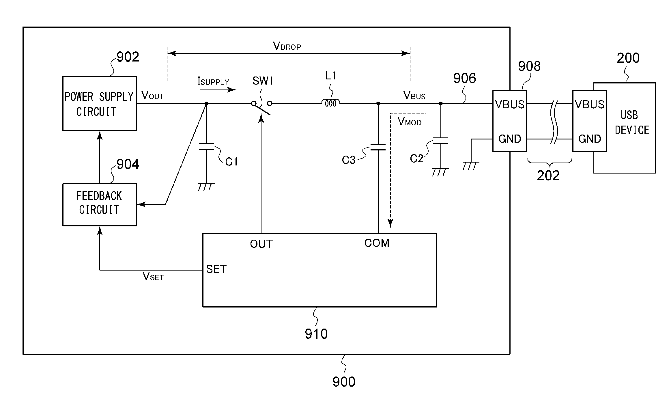
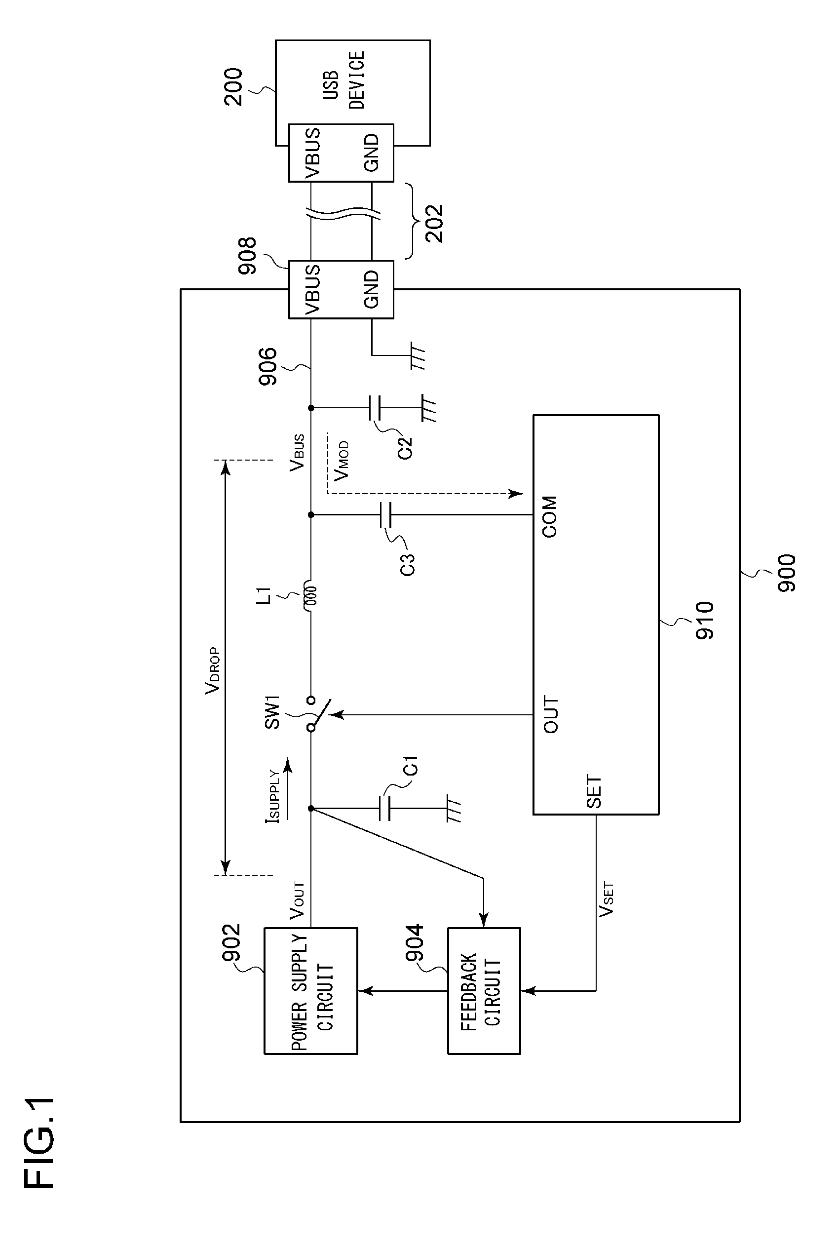
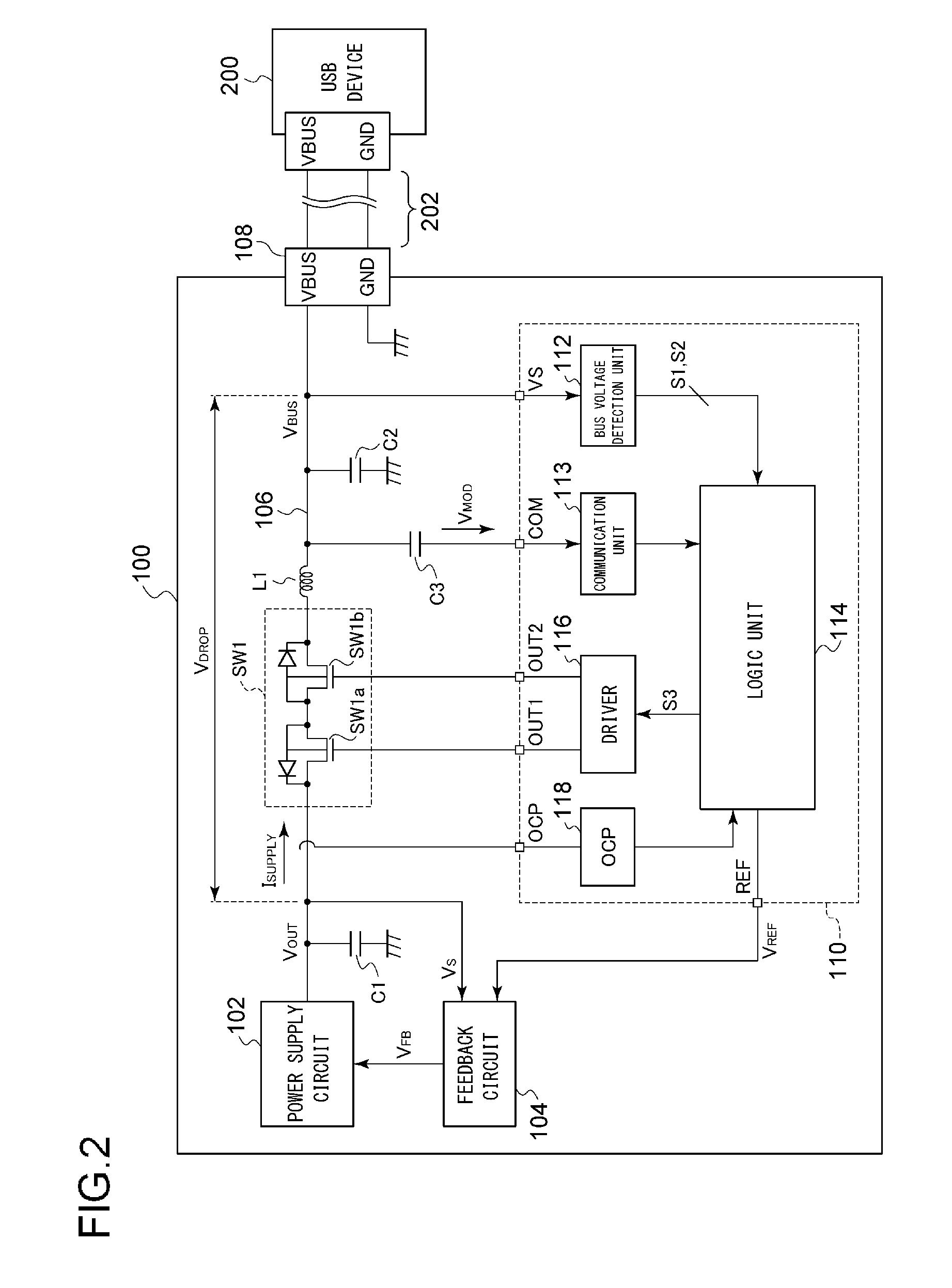
[0091]FIG. 5 is a block diagram showing a USB power supply apparatus 100a according to a first modification. Description will be omitted regarding the same configuration as that shown in FIG. 2. Only the points of difference will be described. In the USB power supply apparatus 100a shown in FIG. 5, a controller 100a further includes a current detection unit 130.

[0092]The current detection unit 130 detects the supply current ISUPPLY. The controller 110a controls the reference voltage VREF based on the detection result obtained by the current detection unit 130, in addition to the detection result obtained by the bus voltage detection unit 112. The current detection unit 130 may detect a current at a position that is closer to the power supply circuit 102 side than the switch SW1. Also, the current detection unit 130 may detect a current at a position that is closer to the receptacle 108 side than the switch SW1. A current detection signal S4 generated by the current detection unit 13...

second modification

[0097]FIG. 6 is a block diagram showing a USB power supply apparatus 100b according to a second modification. In the USB power supply apparatus 100b shown in FIG. 5, a controller 110b further includes an output voltage detection unit 132. The output voltage detection unit 132 detects the output voltage VOUT of the power supply circuit 102. The logic unit 114 controls the reference voltage VREF based on the detection result obtained by the output voltage detection unit 132, in addition to the detection results (S1 and S2) obtained by the bus voltage detection unit 112. A voltage detection signal S5 generated by the output voltage detection unit 132 may be a signal that represents the result of a comparison of the output voltage VOUT of the power supply circuit 102 with a predetermined threshold value. Also, the voltage detection signal S5 may be configured as a digital value obtained by quantizing the output voltage VOUT.

[0098]A combination of the bus voltage detection unit 112 and t...

third modification

[0100]Description has been made with reference to FIG. 5 regarding the USB power supply apparatus 100a employing both the bus voltage detection unit 112 and the current detection unit 130. Also, the bus voltage detection unit 112 may be omitted. In this case, the reference voltage VREF may be controlled according to the detection result S4 obtained by the current detection unit 130 alone. In a case in which the impedances of the switch SW1 and the inductor L1 are known, the information with respect to the impedances may be stored in the logic unit 114. With such an arrangement, the logic unit 114 may calculate the voltage drop VDROP by multiplying the measurement value of the supply current ISUPPLY by the impedance thus stored, and may set the reference voltage VREF based on the voltage drop VDROP thus calculated.


PUM


Abstract

A USB power supply apparatus supplies electric power to a USB power reception apparatus. A bus line connects the output of the power supply circuit and the USB power reception apparatus. A switch is provided on a path of the bus line. A feedback circuit feedback controls the power supply circuit such that the output voltage VOUT of the power supply circuit approaches a reference voltage VREF. A controller adaptively controls the reference voltage VREF based on an electrical state of the USB power supply apparatus.

Description

[0001]This application is based upon and claims the benefit of priority under 35 U.S.C. §119 from the prior Japanese Patent Application No. 2014-217688, filed Oct. 24, 2014, the entire contents of which are incorporated herein by reference.BACKGROUND OF THE INVENTION[0002]1. Field of the Invention[0003]The present invention relates to a USB power supply apparatus.[0004]2. Description of the Related Art[0005]Battery-driven devices such as cellular phone terminals, tablet terminals, laptop computers, and portable audio players each include a chargeable secondary battery and a charger circuit that charges the secondary battery as built-in components. Known examples of such charger circuits include an arrangement that charges a secondary battery using a DC voltage (bus voltage VBUS) supplied from an external circuit via a USB (Universal Serial Bus) cable.[0006]At present, as a charger circuit mounted on a mobile device, charger circuits that conform to a specification which is referred ...

Claims


Application Information

Patent Timeline
IPC IPC(8): G05F1/575
CPCG05F1/575
Inventor MOTOKI, KENICHI
Owner ROHM CO LTD
Why Eureka
Try Eureka