Direct type backlight with support rods integral with diffuser board

a backlight and diffuser board technology, applied in the field of backlight modules, can solve the problems of high manufacturing cost, inconvenient manufacturing, and difficulty in keeping the top end of the support member d in flush, and achieve the effect of being cheap to manufactur

Active Publication Date: 2007-05-15
AU OPTRONICS CORP
View PDF6 Cites 7 Cited by
  • Summary
  • Abstract
  • Description
  • Claims
  • Application Information

AI Technical Summary

Benefits of technology

[0005]The present invention has been accomplished under the circumstances in view. It is one object of the present invention to provide a back light module, which protects the diffuser board against deformation. It is another object of the present invention to provide a back light module, which is inexpensive to manufacture. To achieve these and other objects of the present invention, the back light module comprises a lamp case, a plurality of lamp tubes fixedly mounted inside the lamp case, and a diffuser board fastened to the top open side of the lamp case and suspending above the lamp tubes. The diffuser board has a plurality of bottom support members formed integral with the bottom wall thereof and respectively stopped at the bottom wall of the lamp case to support the diffuser board against deformation.

Problems solved by technology

According to this design, lamp tubes B are fixedly mounted inside a casing A, and a diffuser board C is suspending above the lamp tubes B. This design of back light module is not satisfactory in function because the diffuser board C tends to curve inwards due to the effect of its gravity weight and ambient temperature and moisture. FIG. 2 shows another design of back light module in which support members D are mounted inside the casing A to support the diffuser board C above the lamp tubes B. This design eliminates the drawback of the design shown in FIG. 1, however its manufacturing cost is high.
Further, because the support members D are respectively and perpendicularly fastened to the bottom wall of the casing A by a respective screw joint, it is difficult to keep the top ends of the support members D in flush.

Method used


Image

  • Direct type backlight with support rods integral with diffuser board
  • Direct type backlight with support rods integral with diffuser board
  • Direct type backlight with support rods integral with diffuser board

Examples


Embodiment Construction

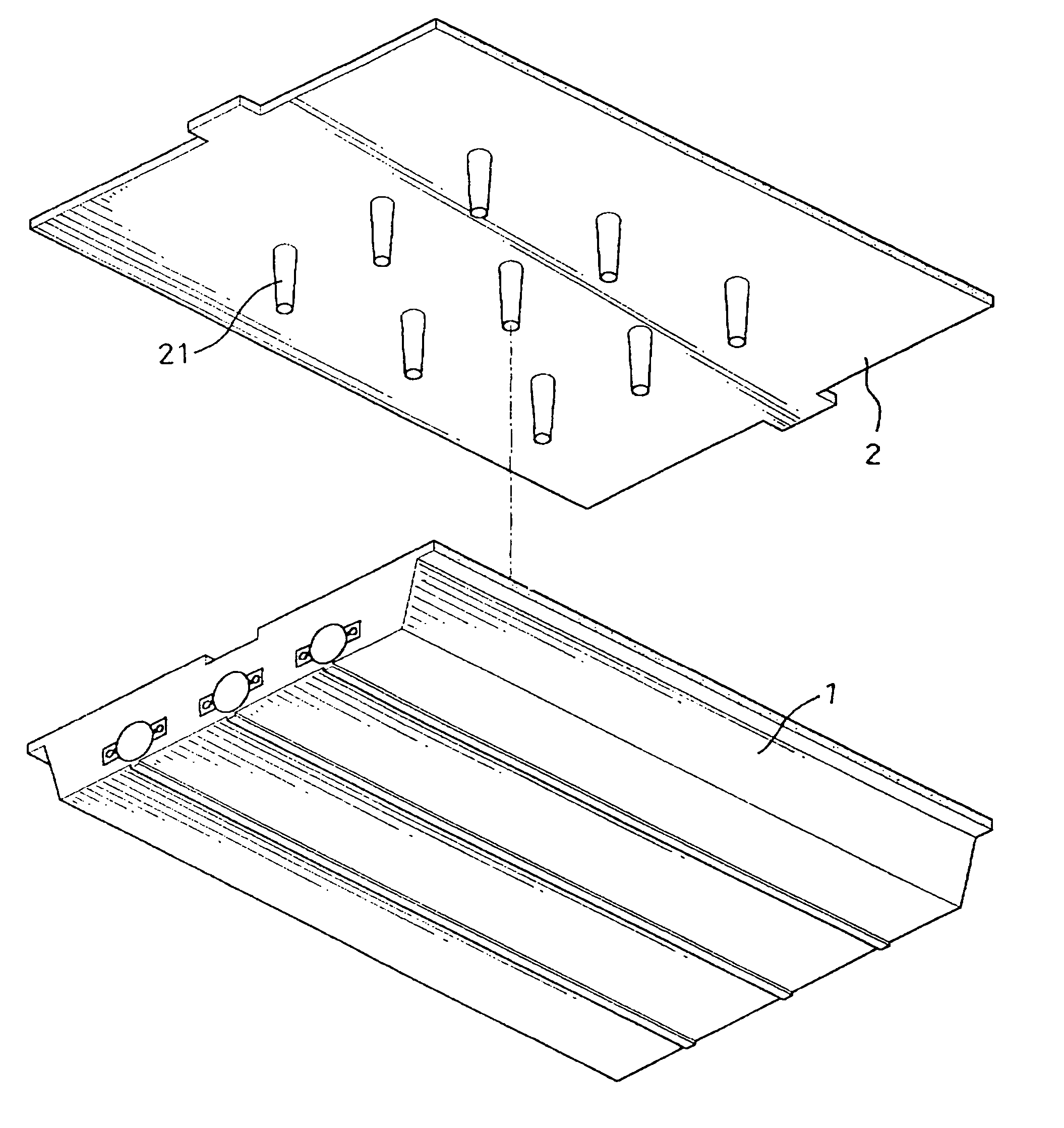
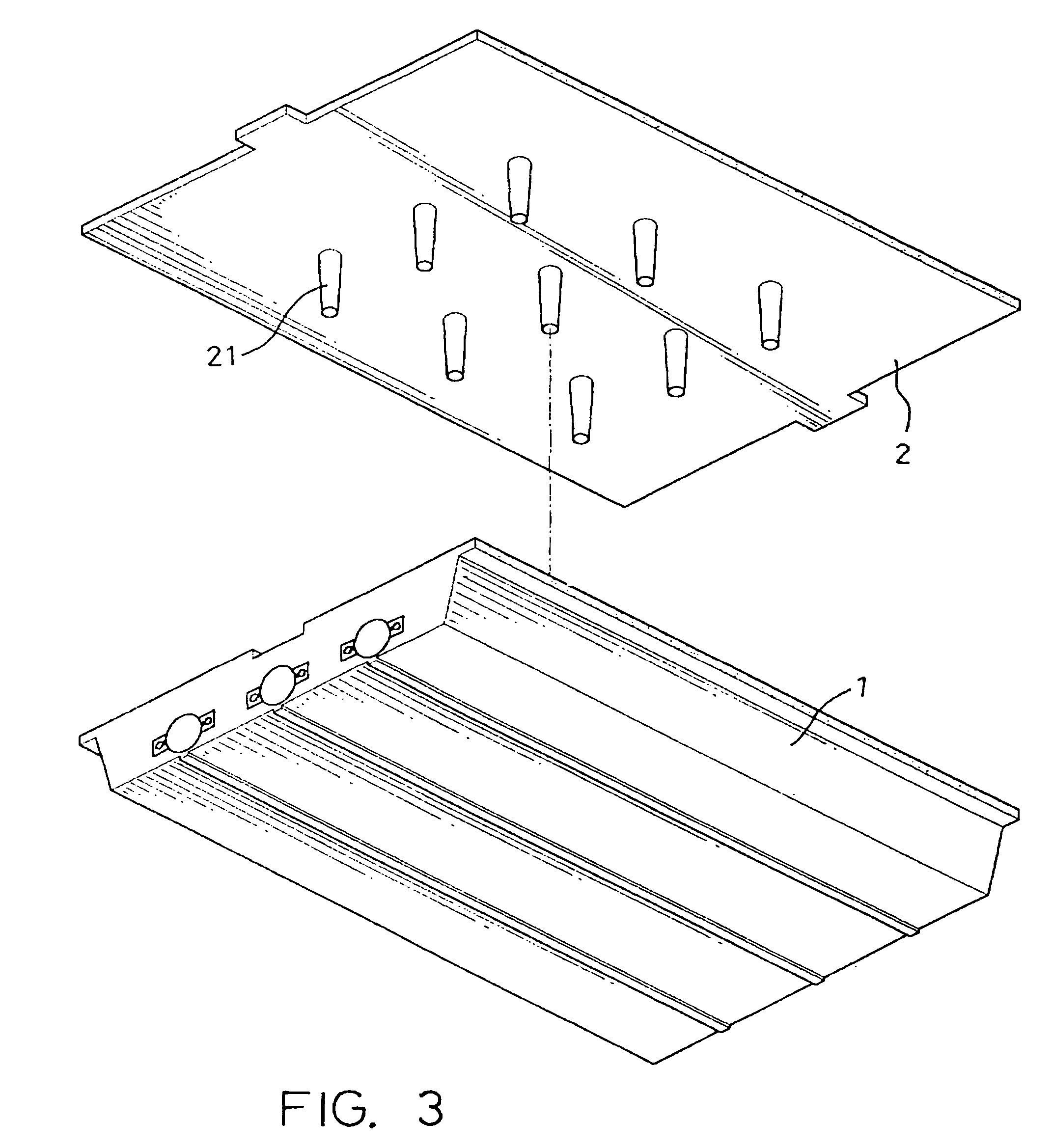
[0011]Referring to FIGS. 3 and 4, a back light module in accordance with the present invention is shown comprised of a lamp case 1, a plurality of lamp tubes (not shown) mounted inside the lamp case 1, and a diffuser board 2 fastened to the top open side of the lamp case 1. The lamp case 1 is preferably made of metal. The diffuser board 2 has a plurality of bottom support rods 21 respectively formed integral with and perpendicularly extended from the bottom sidewall thereof to a distance corresponding to the depth of the lamp case 1. The bottom support rods 21 are equal in length (height). The bottom support rods 21 are preferably injection molded with the diffuser board 2 from acrylics.

[0012]When the diffuser board 2 covered on the top open side of the lamp case 1, the bottom support rods 21 are positively stopped at the bottom wall of the lamp case 1 to support the diffuser board 2 in shape, preventing deformation of the diffuser board 2 due to the effect of ambient temperature an...


PUM

PropertyMeasurementUnit
shapeaaaaaaaaaa
gravity weightaaaaaaaaaa
temperatureaaaaaaaaaa

Abstract

A back light module in which the diffuser board has integrated bottom support rods that are stopped at the bottom wall of the lamp case of the back light module to support the diffuser board in shape and to protect the diffuser board against deformation when the diffuser board installed in the lamp case.

Description

BACKGROUND OF THE INVENTION[0001]1. Field of the Invention[0002]The present invention relates to a back light module, and more particularly, to a back light module in which the diffuser board has bottom support rods that support the diffuser board in shape.[0003]2. Description of the Related Art[0004]A back light module is an essential assembling component of the display screen of a notebook computer or LCD monitor, generally including a lampshade or lamp case, lamp tubes fixedly mounted in the lampshade or lamp case, and a diffuser board (light guide plate). FIG. 1 illustrates a back light module according to the prior art. According to this design, lamp tubes B are fixedly mounted inside a casing A, and a diffuser board C is suspending above the lamp tubes B. This design of back light module is not satisfactory in function because the diffuser board C tends to curve inwards due to the effect of its gravity weight and ambient temperature and moisture. FIG. 2 shows another design of...

Claims


Application Information

Patent Timeline
Patent Type & Authority Patents(United States)
IPC IPC(8): G09F13/04F21V17/10G02F1/1335G02F1/13357
CPCF21V17/10G02F1/133606F21Y2103/00
Inventor WU, CHIH-KANG
Owner AU OPTRONICS CORP
Why Eureka
Try Eureka