

Management of live remote medical display
- Summary
- Abstract
- Description
- Claims
- Application Information
AI Technical Summary
Benefits of technology
Problems solved by technology
Method used
Image

Examples
Example
[0021]Corresponding reference numerals indicate corresponding parts throughout the several views of the drawings.
DETAILED DESCRIPTION OF THE INVENTION
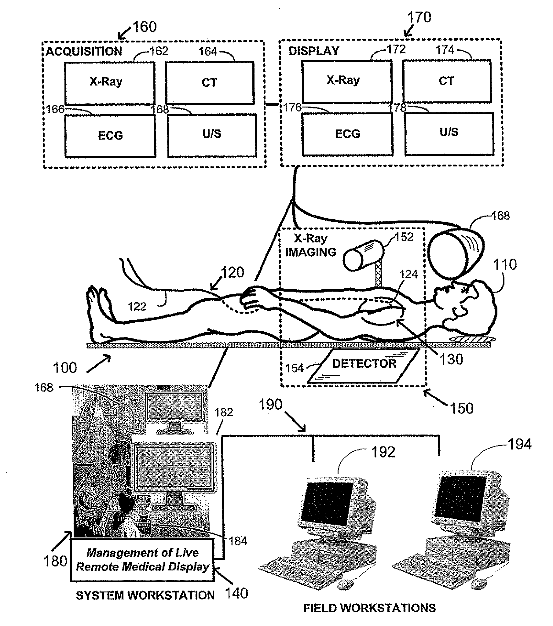
[0022]As illustrated in FIG. 1, a patient 110 is positioned within a remotely actuated, computer controlled imaging and interventional complex medical system 100. An elongated navigable medical device 120 having a proximal end 122 and a distal end 124 is provided for use in the minimally invasive interventional system 100 and the medical device is inserted into a blood vessel of the patient and navigated to an intervention volume 130. For illustration of one embodiment, in magnetic navigation a magnetic field externally generated by magnet(s) assembly 168 orients a small magnetically responsive element (not shown) located at or near the device distal end 124. Real-time information is provided to the physician by at least one imaging sub-system 150, for illustration an x-ray imaging apparatus comprising an x-ray tube 152 and a digital x...
PUM
 Abstract
Description
Claims
Application Information