Soldering Device with Cartridge Type Battery Pac

a technology of soldering device and cartridge type, which is applied in the direction of ohmic resistance heating, solventing apparatus, manufacturing tools, etc., can solve the problems of lack of ac power supply, lack of portability of non-ac powered devices, and limited performance of industrial soldering devices

Inactive Publication Date: 2009-01-15
MIYAZAKI MITSUHIKO +3
View PDF38 Cites 5 Cited by
  • Summary
  • Abstract
  • Description
  • Claims
  • Application Information

AI Technical Summary

Problems solved by technology

However, there are a few battery powered soldering devices that are available though their performance is somewhat limited.
The need for a soldering device which can provide the performance of industrial soldering irons with the portability of a non-AC powered device have been somewhat limited.
For the battery powered types of soldering devices, the various styles available are also somewhat limited as they do not include the flexibility which may be desired for hobbyists as well as professional users and craftsmen.

Method used


Image

  • Soldering Device with Cartridge Type Battery Pac
  • Soldering Device with Cartridge Type Battery Pac
  • Soldering Device with Cartridge Type Battery Pac

Examples


Embodiment Construction

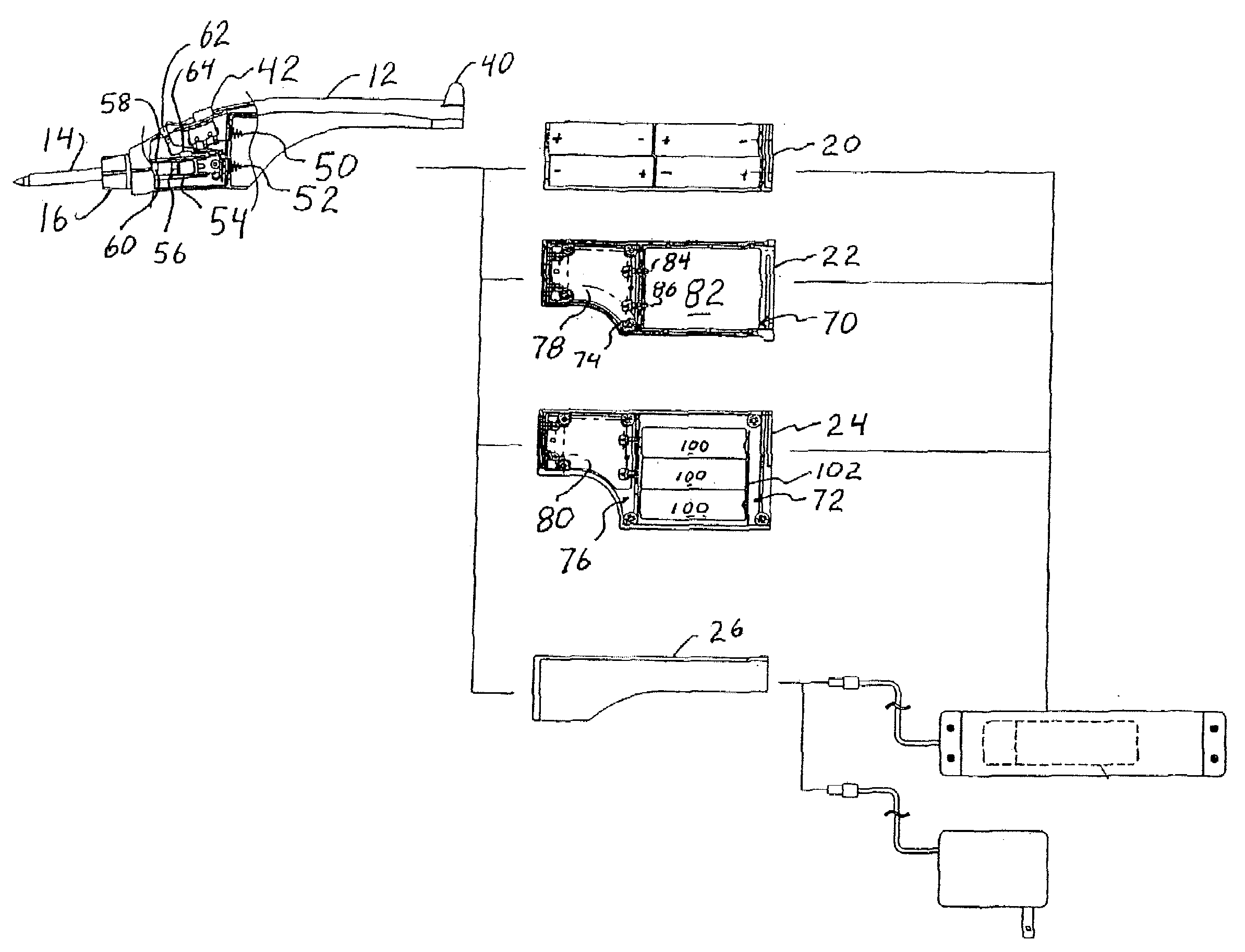
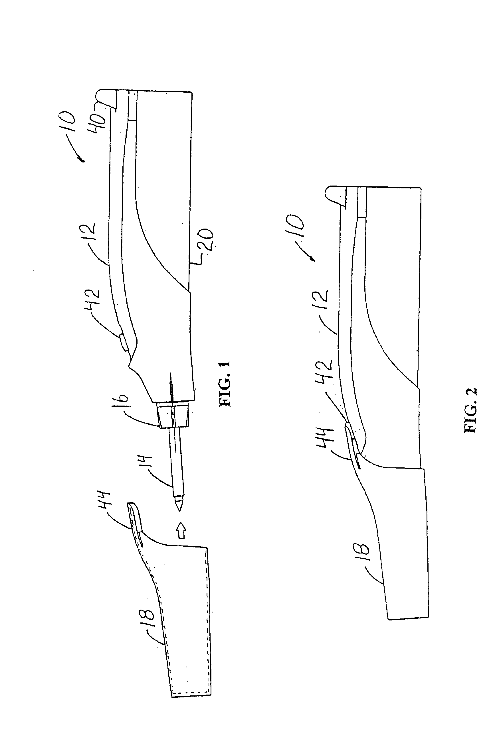
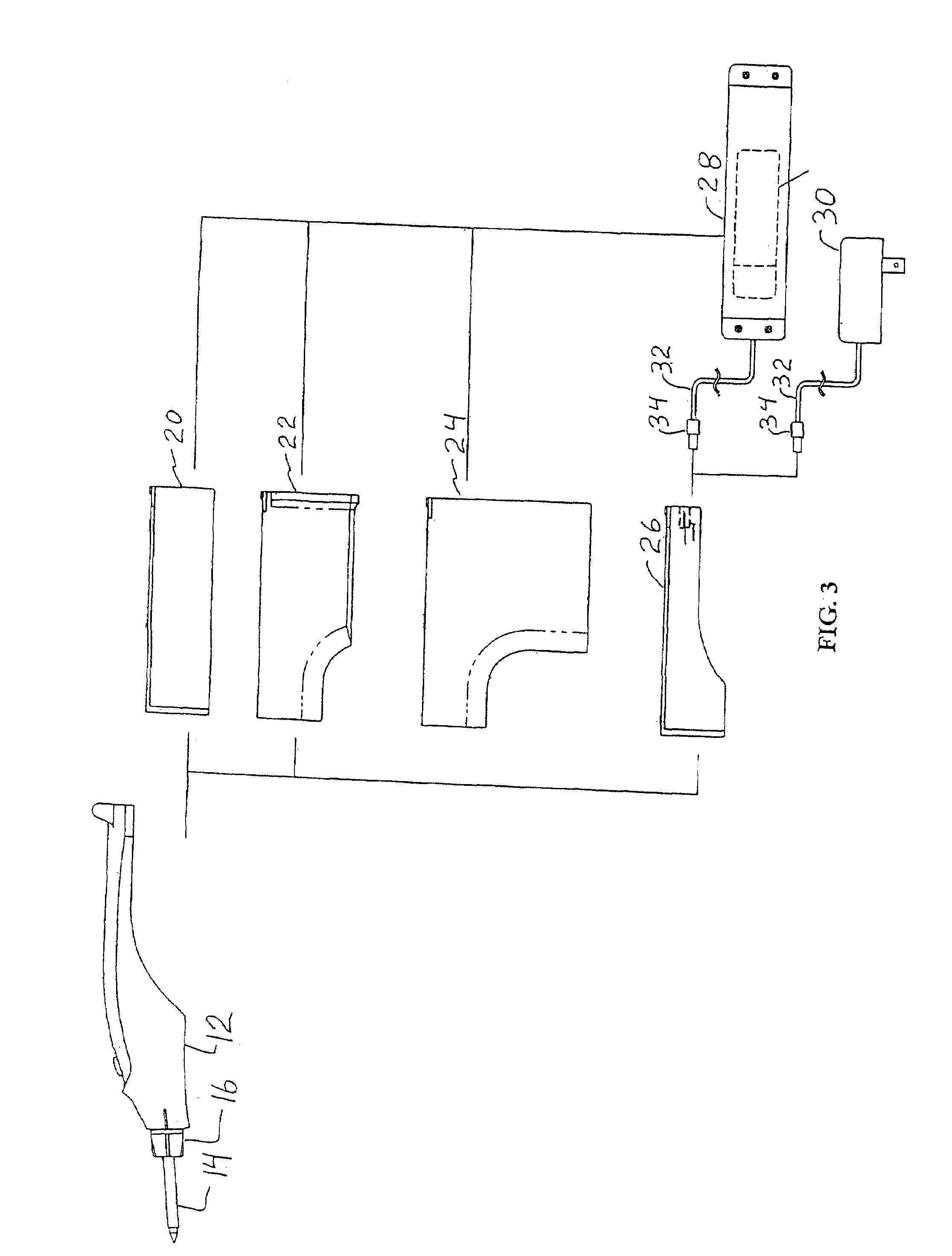
[0014]FIGS. 1 and 2 depict side views of a soldering device 10 according to the present invention. The soldering device 10 includes a handle 12 onto which a cartridge soldering tip 14 may be mounted by the use of a securing nut 16. The soldering device preferably includes a protection cap 18 shown removed in FIG. 1 and shown attached in FIG. 2 to the handle 12. The protection cap 18 covers the cartridge soldering tip 14 when it is not in use.

[0015]The soldering device 10 also includes a battery cartridge 20 which is removably attached to the handle 12. The battery cartridge 20 provides the electrical power for heating the cartridge soldering tip 14.

[0016]The battery cartridge 20 depicted in FIGS. 1 and 2 is preferably configured to contain four AA batteries arranged in two rows of two batteries placed end to end. The AA batteries may be either the non-rechargeable alkaline batteries or rechargeable nickel hydride batteries.

[0017]The battery cartridge 20 is removable and indeed repla...


PUM


Abstract

A method of configuring a soldering device includes the steps of purchasing (or offering for sale) a soldering device package including a handle, a power cartridge containing an AA battery, a power cartridge containing a lithium ion battery, and a power cartridge containing a nickel-hydride battery; selecting (or instructing a user to select) one of the three power cartridges from the purchased soldering device package for use with the handle to form a soldering device; and inserting the selected power cartridge in the handle to form a soldering device. The selecting step includes selecting one of the three power cartridges based on a specific use of the soldering device and based on soldering performance requirements of the specific use and based on operating times and relative costs of the power cartridges.

Description

[0001]The present application is a division of U.S. patent application Ser. No. 10 / 892,780, filed Jul. 15, 2004, the entire disclosure of which application is incorporated herein by reference.BACKGROUND OF THE INVENTION[0002]Soldering irons are used to make secure electrical connections by melting solder and allowing the solder to bond between two electrical devices such as wires and contact points of a circuit. A number of different types of soldering irons are in wide-spread use and have been available for a number of years. Most soldering devices are powered by electrical current, and particularly for industrial applications, the soldering devices use an AC power source. However, there are a few battery powered soldering devices that are available though their performance is somewhat limited. Examples are shown in U.S. Pat. Nos. 2,973,422; 3,141,087; 3,141,956; 4,064,447 and 5,446,262. In addition, to provide flexibility in a soldering device that has no electrical power connecti...

Claims


Application Information

Patent Timeline
Patent Type & Authority Applications(United States)
IPC IPC(8): H05B1/00
CPCB23K3/0323B23K3/0369B23K3/0346
Inventor MIYAZAKI, MITSUHIKOTERAOKA, YOSHITOMOKATO, TADASHIYAMANAKA, TSUYOSHI
Owner MIYAZAKI MITSUHIKO
Why Eureka
Try Eureka