
Redundant power supply system

Inactive Publication Date: 2009-01-15
ZIPPY TECH
View PDF3 Cites 4 Cited by
  • Summary
  • Abstract
  • Description
  • Claims
  • Application Information

AI Technical Summary

Benefits of technology

[0005]Therefore the primary object of the present invention is to provide a redundant power supply system that can balance DC power output from main power units to achieve optimal output quality and also balance stationary power output from individual stationary power units that have increasing load so that total output power can be optimized. And power loss of important equipment can be avoided caused by interruption of any main power unit or stationary power unit.

Problems solved by technology

The general electric equipments that need a great amount electric power such as industrial computers or computers used on aircrafts require a steady and reliable power supply due to they have to continuously process huge and complex information.
But in practice, any of the main power units could be aged or encounter variation of output impedance that cause even sharing of the power not possible.
To force them to evenly supply the same amount of power could cause overload of the main power unit.
This greatly shortens the life span of the redundant power supply system.
As the electric equipments become more complex and require increasing amount of power, demand on the stationary power unit also increases.
As a result, the stationary power units also might encounter the condition of unbalanced power supply happened to the main power units previously discussed, and a forced and overloaded output power supply could shorten the life span of the standby power units.
Power supply in the regular condition could also be impacted.
Overload of the stationary power units could also result in abrupt power interruption.
And the electronic elements in the electric equipments that rely on the power of the stationary power units could lose voltage instantly and be damaged.

Method used


Image

  • Redundant power supply system
  • Redundant power supply system
  • Redundant power supply system

Examples


Embodiment Construction

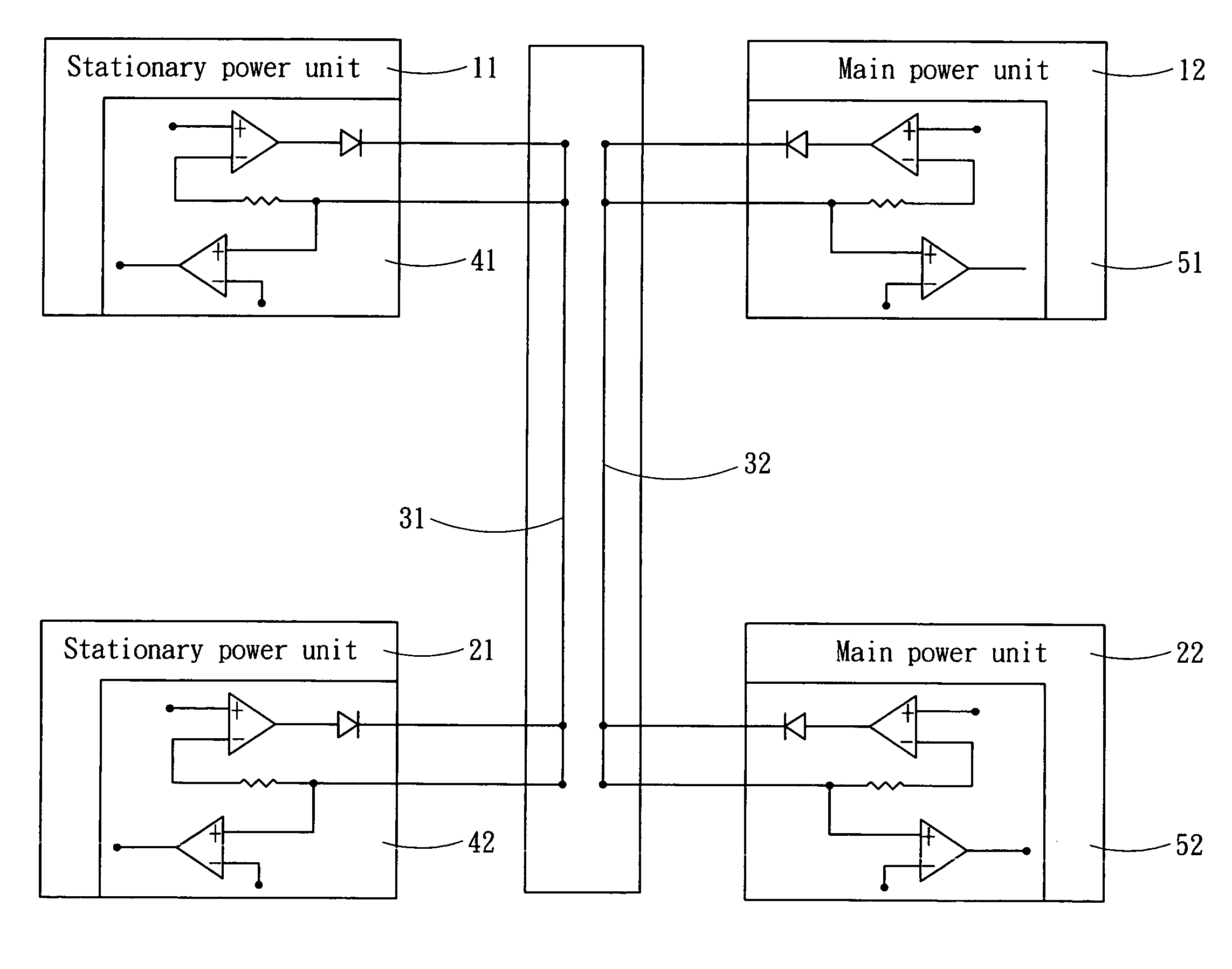
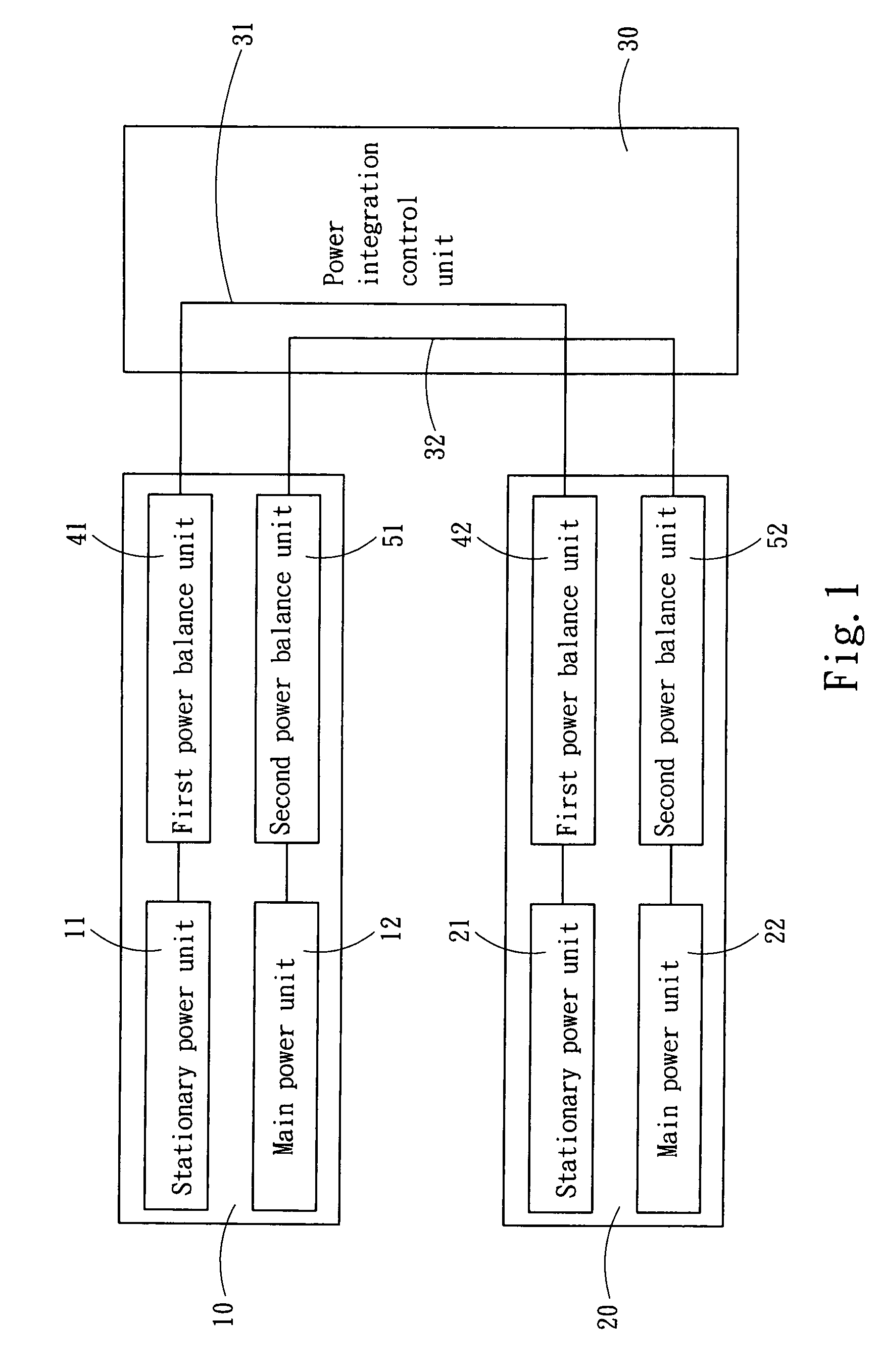
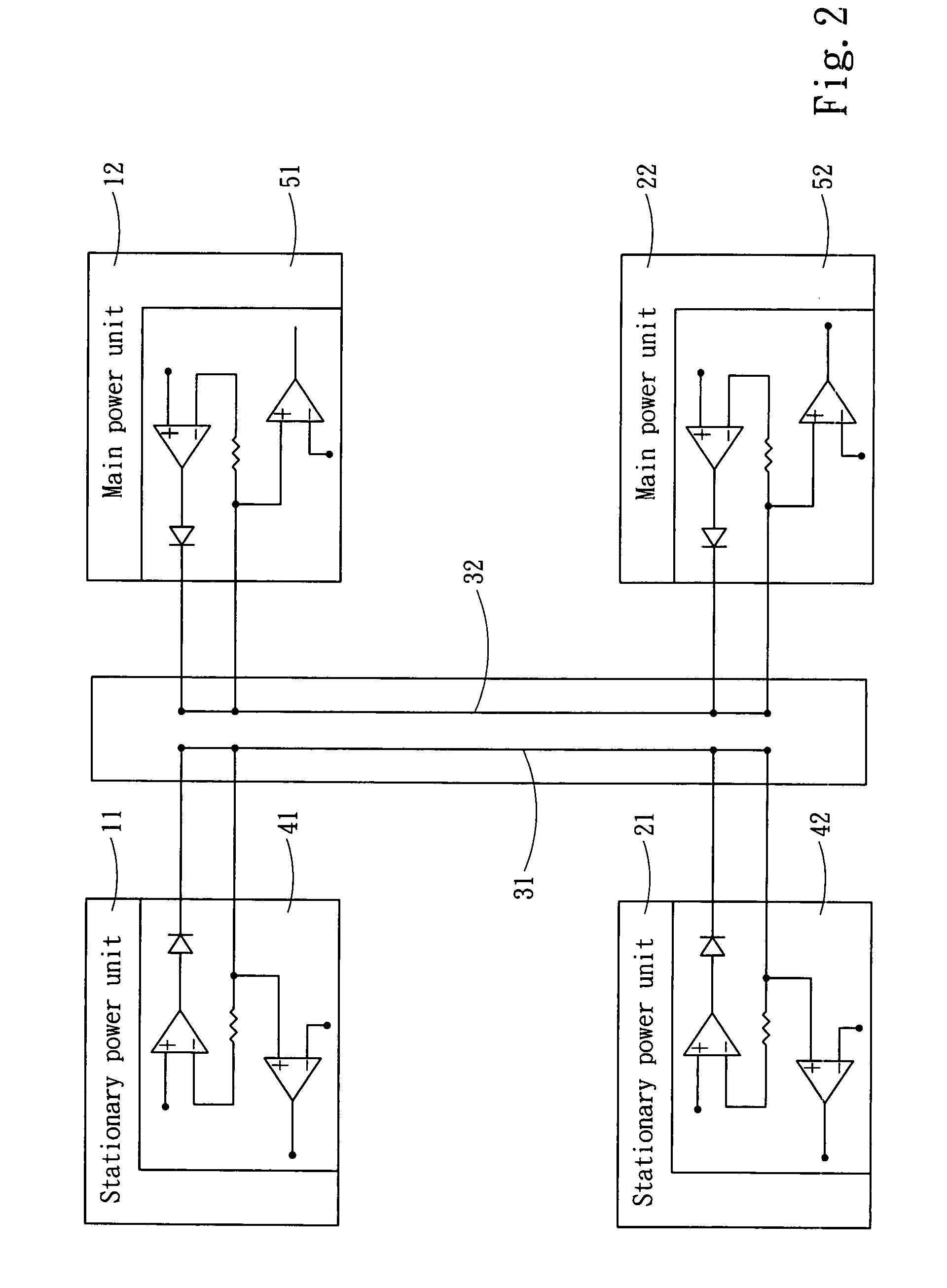
[0010]Please refer to FIGS. 1 and 2, the redundant power supply system of the invention has N+M sets of power supply devices 10 and 20, in which N≧1 and M≧1. N represents the number of the power supply devices 10 to meet total power load requirements for driving electric equipments. M represents the allowable number of the power supply devices 20 that can be out of service. The power supply devices 10 and 20 are connected to at least one external power source to transform power to be output. The power supply devices 10 and 20 have respectively a power transformation unit which includes at least a stationary power unit 11 and 21, and a main power unit 12 and 22. The stationary power units 11 and 21 are connected to the external power source during the power supply devices 10 and 20 in a standby mode to output the transformed power in regular conditions. The main power units 12 and 22 are connected to the external power source to output the transformed power in a power ON condition. T...


PUM


Abstract

A redundant power supply system aims to balance power supply among main power units and stationary power units to achieve optimum output quality for the main power units and stationary power units, and also prevent interruption of power supply resulting from any main power units or stationary power units. It includes a power integration control unit. The power integration control unit and the main power units and stationary power units are bridged respectively by a power balance unit which functions in a load power balance mode such that the power integration control unit outputs a total output power in power ON and standby conditions, and each power supply device delivers actual output power according to the load ratio of the power supply device.

Description

FIELD OF THE INVENTION[0001]The present invention relates to a redundant power supply system and particularly to a redundant power supply system equipped with a power balance unit.BACKGROUND OF THE INVENTION[0002]The general electric equipments that need a great amount electric power such as industrial computers or computers used on aircrafts require a steady and reliable power supply due to they have to continuously process huge and complex information. To prevent abrupt loss of power supply or instant pulse resulting from switching to backup power that might damage the expensive electric equipments or cause instant loss of information under processing, a N+M redundant power supply system is generally adopted to maintain regular operation without interrupting the power supply. N represents the number of power supply devices assembled to meet total power loading requirement of the electric equipments. M represents the allowable number of power supply devices that can be out of servi...

Claims


Application Information

Patent Timeline
IPC IPC(8): G06F1/26
CPCH02J1/108G06F1/263
Inventor CHEN, TSUNG-CHUN
Owner ZIPPY TECH
Learn More