Coupling device for circular pipes

Active Publication Date: 2009-01-22
KOFULSO
View PDF1 Cites 35 Cited by
  • Summary
  • Abstract
  • Description
  • Claims
  • Application Information

AI Technical Summary

Benefits of technology

[0009]The present invention has been made to solve the foregoing problems with the prior art, and therefore an object of the present invention is to provide a coupling device for circular pipes, in which locking rings, inserted into a body to clamp a circular pipe, are arranged in a pair so that the central line of a circular pipe can be aligned when the circular pipe is inserted, and the extent to which the body presses the seal packing can be adjusted so that a seal can be satisfactorily main

Problems solved by technology

However, in order to separate the circular pipe, it is required to break the body of the coupling device or cut

Method used


Image

  • Coupling device for circular pipes
  • Coupling device for circular pipes
  • Coupling device for circular pipes

Examples


Embodiment Construction

[0024]The present invention will now be described more fully with reference to the accompanying drawings, in which preferred embodiments of the invention are shown.

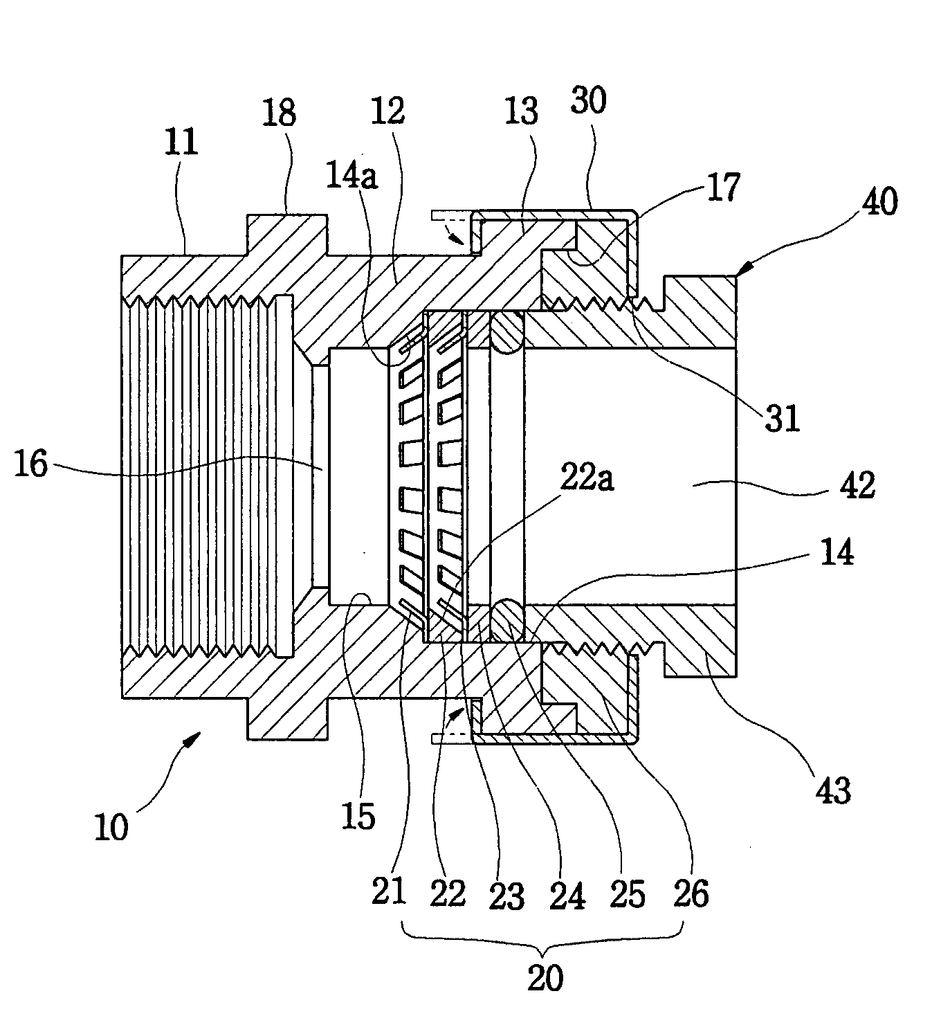
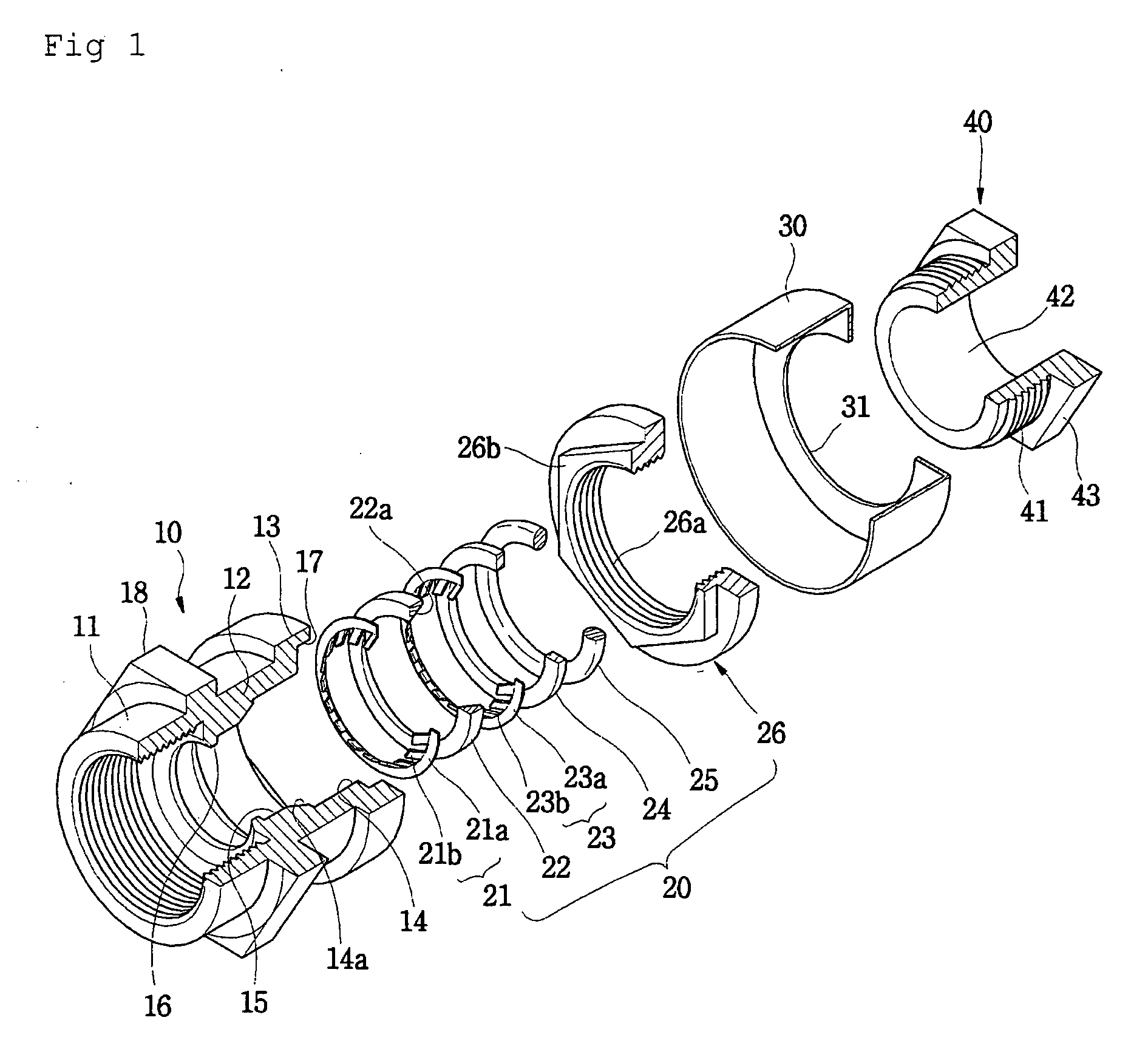
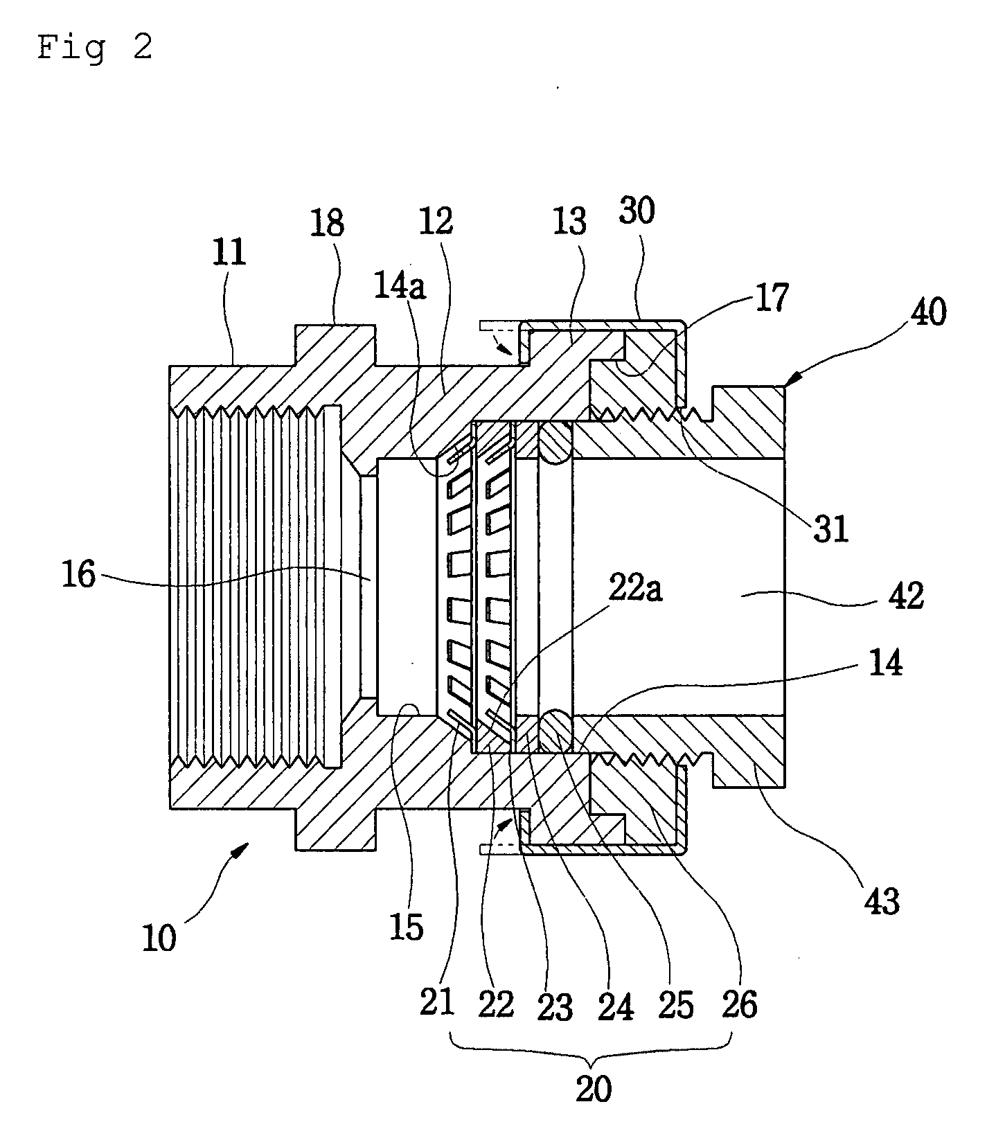
[0025]FIG. 1 is an exploded perspective view illustrating a coupling device according to an embodiment of the present invention, and FIG. 2 is a cross sectional view illustrating the coupling device shown in FIG. 1 in an assembled state. Referring to FIGS. 1 and 2, the coupling device of the present invention includes a body 10, a circular pipe locking means 20, a fixing member 30 and an adjustment member 40. The body 10 includes a first coupling section 11 at one portion thereof, a second coupling section 12 at another portion thereof, a flange 13 protruding from an end of the second coupling section 12, a coupling hole 14 formed in the second coupling section 12, a circular pipe coupling hole 15 extending from the coupling hole 14 and a connecting hole 16 extending from the circular pipe coupling hole 15 through the fir...


PUM


Abstract

A coupling device for circular pipes, in which locking rings, inserted into a body to clamp a circular pipe, are arranged in a pair so that the central line of a circular pipe can be aligned when the circular pipe is inserted. Furthermore, the degree to which the body presses the seal packing can be adjusted so that a reliable seal can be maintained and the circular pipe can be securely coupled no matter who uses the coupling device. A coupling device for corrugated and circular pipes is provided for the case where it is more effective to replace one of the circular pipes with a corrugated pipe. The first coupling section and a connecting means, which can engage with a corrugated pipe, are provided opposite the second coupling section, which is coupled with the circular pipe.

Description

BACKGROUND OF THE INVENTION[0001]1. Field of the Invention[0002]The present invention relates to a coupling device for circular pipes, and more particularly to a coupling device for circular pipes, in which a pair of locking rings is arranged to clamp a circular pipe and a body for receiving the circular pipe is configured to press a packing in order to ensure a seal.[0003]2. Description of the Related Art[0004]As well known in the art, in a conventional coupling device for circular pipes, a packing, a support ring and a locking ring are inserted sequentially into a body, and a nut having an entrance hole is engaged with the body so that the packing maintains a seal and the locking ring clamps a circular pipe. With the circular pipe inserted into the coupling device through the entrance hole, the locking ring exerts a locking force on the circular pipe so that it is not separated from the coupling device even if an external force is applied in a direction opposite to a direction of ...

Claims


Application Information

Patent Timeline
IPC IPC(8): F16L55/00
CPCF16L19/086F16L37/091F16L25/0036
Inventor OH, SEUNG-IL
Owner KOFULSO
Why Eureka
Try Eureka