Driving apparatus

a technology of driving apparatus and electric motor, which is applied in the direction of piezoelectric/electrostrictive/magnetostrictive devices, electrical apparatus, piezoelectric/electrostriction/magnetostriction machines, etc., can solve the problems of difficult expansion and contraction, serious problems, etc., and improve the supporting stability of the electromechanical conversion element. , the effect of expanding and contracting the electromechanical conversion elemen

Inactive Publication Date: 2009-01-22
FUJI PHOTO OPTICAL CO LTD
View PDF10 Cites 5 Cited by
  • Summary
  • Abstract
  • Description
  • Claims
  • Application Information

AI Technical Summary

Benefits of technology

[0009]Therefore, the invention has been conceived in view of the background thus far described, and has an object to provide a driving apparatus, which can make the expansion and contraction of the electromechanical conversion element larger and which can improve the supporting stability of the electromechanical conversion element better.

Problems solved by technology

As a result, the electromechanical conversion element is improved in its supporting stability, but finds it difficult to make its expansion and contraction larger.
Therefore, a dislocation, as caused in the electromechanical conversion element by shocks due to a fall or the like, raises a serious problem even if the dislocation is small.

Method used


Image

  • Driving apparatus
  • Driving apparatus
  • Driving apparatus

Examples


first embodiment

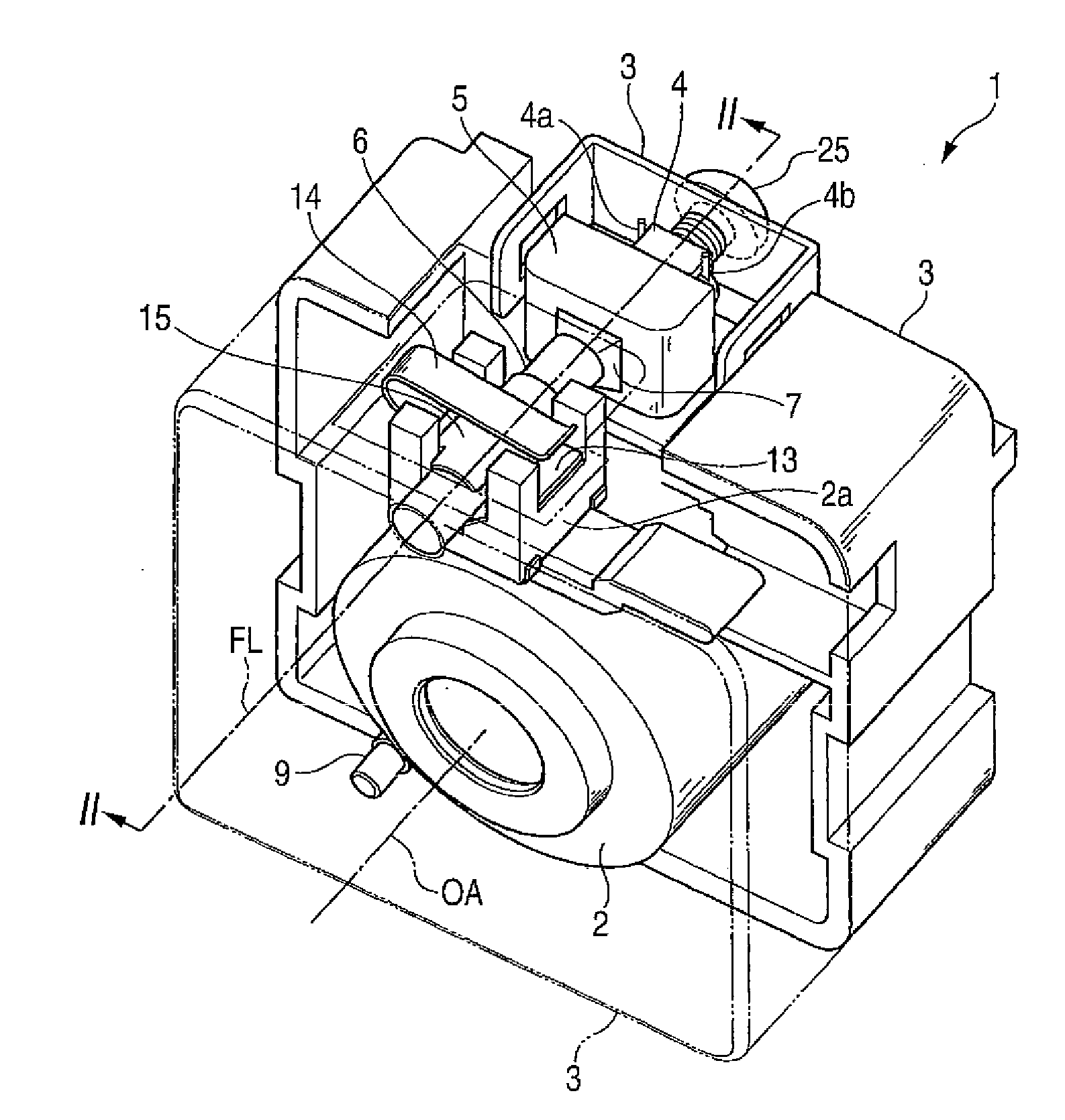
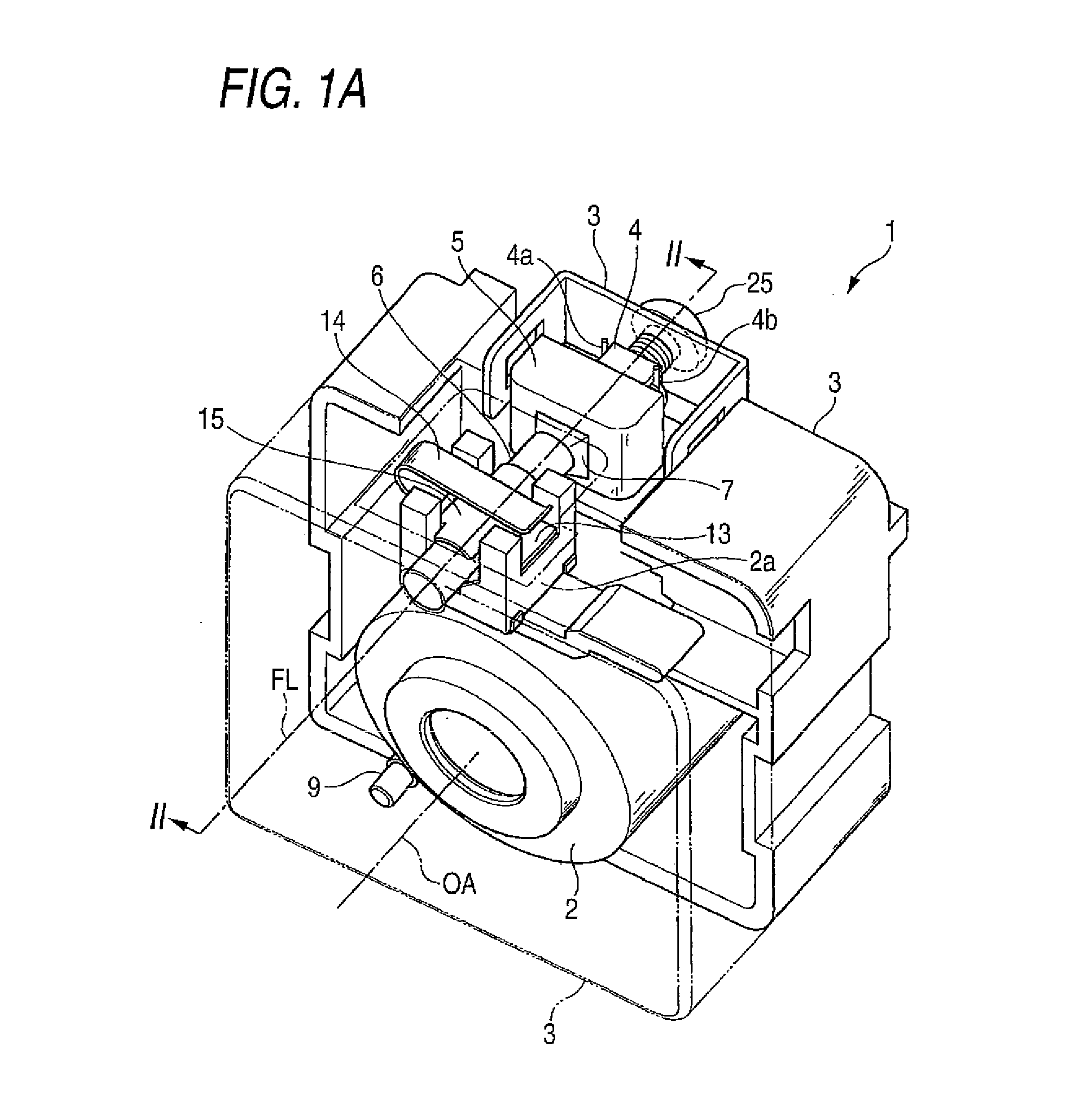
[0031]In the first embodiment, as shown in FIG. 1A and FIG. 2A, the piezoelectric element 4 is provided, on its other side in the extending direction of the fiducial line FL, with a screw (or an urging member) 25, which is so fastened in the holder 3 as to push the other end of the piezoelectric element 4. The screw 25 urges the piezoelectric element 4 toward the one side of the extending direction of the fiducial line FL.

second embodiment

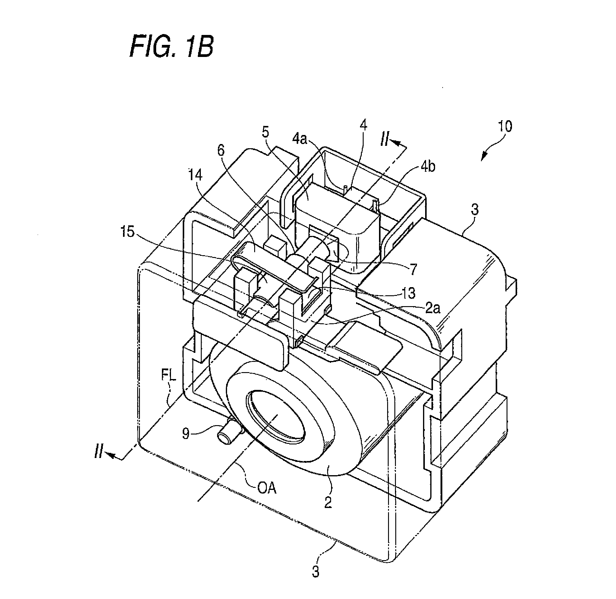
[0032]In the second embodiment, as shown in FIG. 1B and FIG. 2B, a support member 20 for supporting the driving shaft 6 is mounted in the bearing hole 11a of the partition 11. This support member 20 is provided with a fixing portion 21 of a rectangular plate shape adhered and fixed to the holder 3, and a fitted portion 22 loosely fitted in the driving shaft 6 from one end side of the same. Between the other end face of the fitted portion 22 and the one end face of the driving shaft 6, there is formed a clearance for keeping those end faces out of contact even when the piezoelectric element 4 extends to its largest stroke. A spring (or an urging member) 26 is arranged in a compressed state in the driving shaft 6 between the one end face of the piezoelectric element 4 and the other end face of the fitted portion 22. The spring 26 urges the piezoelectric element 4 toward the other side of the extending direction of the fiducial line FL. Here, the fixture of the fixing portion 21 on the...


PUM


Abstract

A driving apparatus comprises: an electromechanical conversion element that expands and contracts in an extending direction of a given fiducial line; a driving shaft mounted on one end of the electromechanical conversion element in the extending direction; a driven member frictionally engaged with the driving shaft; a holder that supports the electromechanical conversion element from lateral sides with respect to extending direction; and an urging member that urges the electromechanical conversion element in the extending direction.

Description

BACKGROUND OF THE INVENTION[0001]1. Field of the Invention[0002]The present invention relates to a driving apparatus suited for driving a lens or the like in a mobile telephone with a camera, a small-sized digital camera or the like.[0003]2. Description of the Related Art[0004]A driving apparatus, as known in the aforementioned technical field of the related art (as referred to JP-A-2006-91210, for example), comprises: an electromechanical conversion element for expanding and contracting in the extending direction of a given fiducial line; a driving shaft arranged on one end side of the electromechanical conversion element in the extending direction of the given fiducial line; a driven member frictionally engaged with the driving shaft; and a holder supporting the electromechanical conversion element and the driving shaft and urging the other end of the electromechanical conversion element and one end of the driving shaft so that the electromechanical conversion element and the driv...

Claims


Application Information

Patent Timeline
Patent Type & Authority Applications(United States)
IPC IPC(8): H02N2/08
CPCH02N2/025
Inventor SASAKI, RYOTA
Owner FUJI PHOTO OPTICAL CO LTD
Why Eureka
Try Eureka