Configuration with a Wearing Hook for Hearing Devices and Associated Method

a technology for hearing devices and hooks, applied in the direction of behind the ear hearing aids, ear supports, electric devices, etc., can solve the problem that hearing devices may have greater amplification reserves, and achieve the effect of easy adjustment of the sound frequency spectrum

Inactive Publication Date: 2009-01-22
SIEMENS MEDICAL EQUIPMENT
View PDF8 Cites 1 Cited by
  • Summary
  • Abstract
  • Description
  • Claims
  • Application Information

AI Technical Summary

Benefits of technology

[0019]This is advantageous in that the sound frequency spectrum can thus be easily adjusted.

Problems solved by technology

As a result, hearing devices may have greater amplification reserves.

Method used


Image

  • Configuration with a Wearing Hook for Hearing Devices and Associated Method
  • Configuration with a Wearing Hook for Hearing Devices and Associated Method
  • Configuration with a Wearing Hook for Hearing Devices and Associated Method

Examples


Embodiment Construction

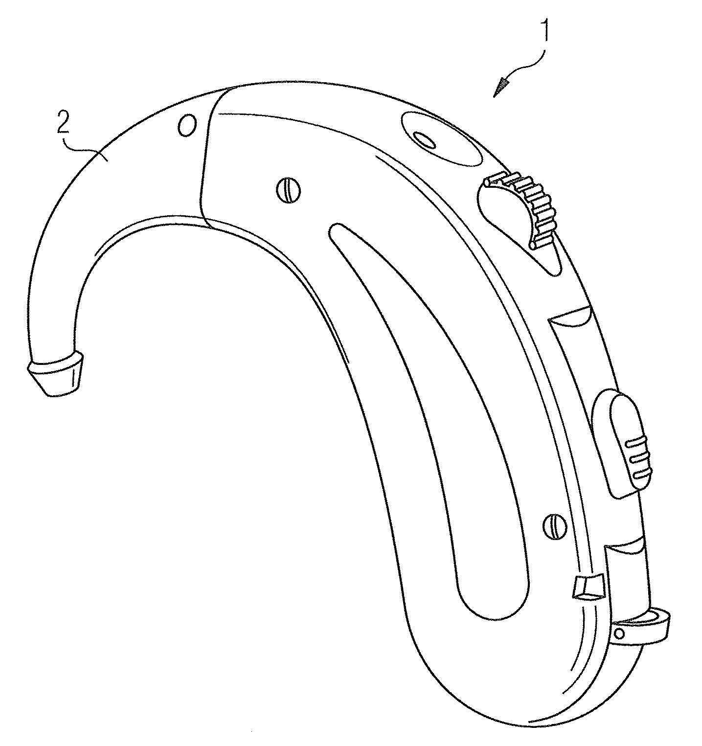
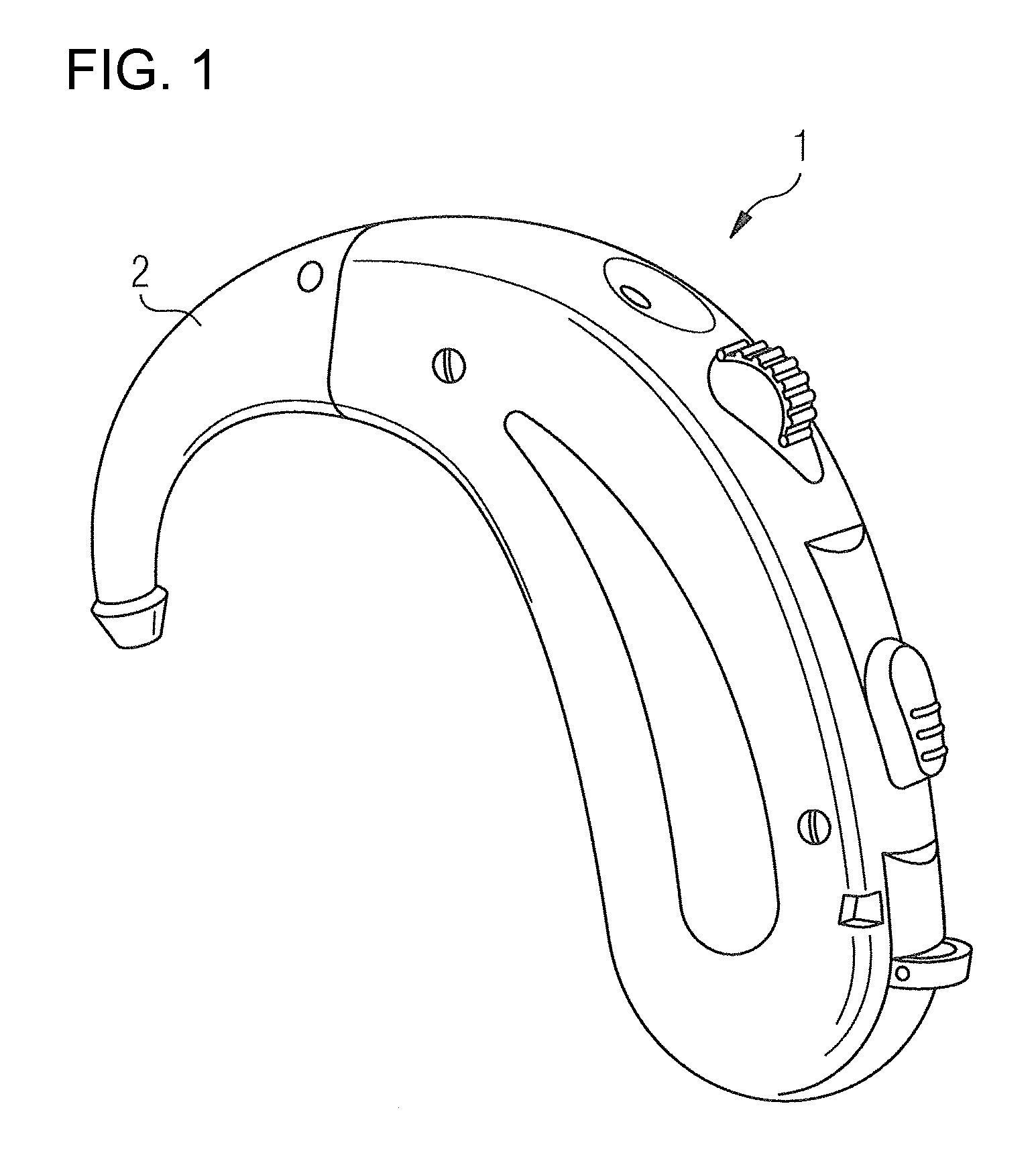
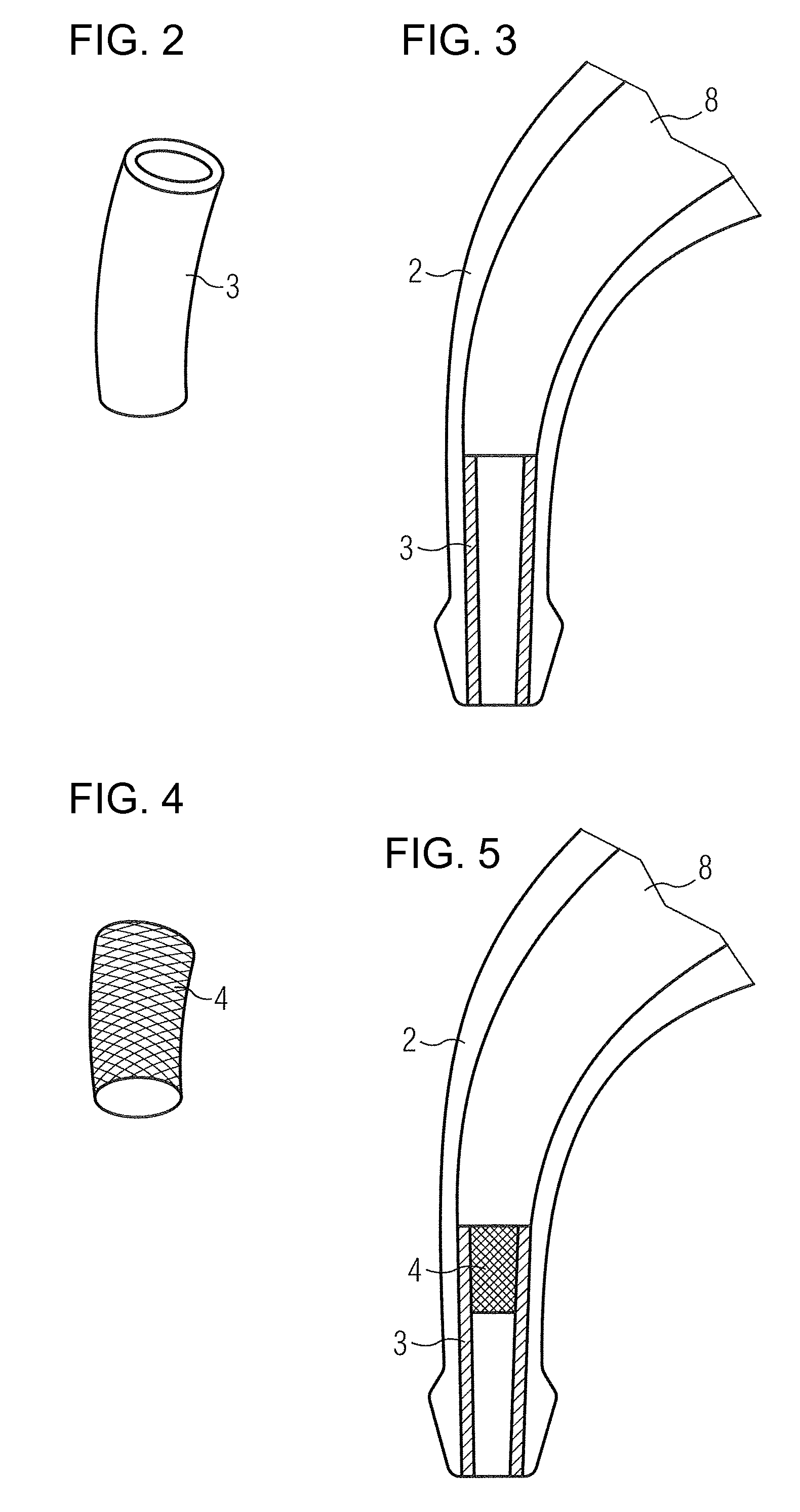
[0033]Referring now to the figures of the drawing in detail and first, particularly, to FIG. 1 thereof, there is shown a behind-the-ear part 1 of a hearing device. An inventive wearing hook 2 with an oscillation-influencing device 3, 5 (not visible) is fastened to the upper end of the behind-the-ear part 1. Acoustic signals are recorded using a microphone of the behind-the-ear part 1 and are supplied to an amplifier circuit as electric signals. After processing and amplifying the electric signals, the signals are converted back in a receiver into acoustic signals and are forwarded via a sound channel of the wearing hook 2.

[0034]A housing end of the hearing device formed by the wearing hook 2 has a truncated cone-shaped thickening at its end, via which a non-illustrated sound tube can be moved, which continues the sound channel to the auditory canal of the hearing device wearer.

[0035]Furthermore, a switch cover, below which a membrane key and a programmable socket are located, and a ...


PUM


Abstract

A wearing hook for hearing devices has at least one device disposed in a sound channel of the wearing hook. The device is able to influence interfering sound-induced oscillations of the wearing hook. The device is for instance a tube made of metal. An associated method is likewise described for influencing the oscillations.

Description

CROSS-REFERENCE TO RELATED APPLICATION[0001]This application claims the priority, under 35 U.S.C. § 119, of German application DE 10 2007 033 289.2, filed Jul. 17, 2007; the prior application is herewith incorporated by reference in its entirety.BACKGROUND OF THE INVENTIONField of the Invention[0002]The invention relates to a wearing hook for a hearing device and a method for influencing oscillations in a wearing hook.[0003]Hearing devices with a behind-the-ear part are generally equipped with a wearing hook to ensure that the behind-the-ear part rests comfortably and securely behind the ear of the hearing device wearer. Aside from the wearing function, the interior of the wearing hook, the so-called sound channel, routes the acoustic signal formed in a receiver of the behind-the-ear part to a sound tube connected to the wearing hook. This is connected to an ear mold.[0004]Excitation using sound waves from an emitted acoustic signal nevertheless causes the wearing hook and / or device...

Claims


Application Information

Patent Timeline
Patent Type & Authority Applications(United States)
IPC IPC(8): H04R25/00
CPCH04R25/02H04R2225/63H04R2225/021H04R25/456H04R2225/0213H04R25/607
Inventor HO, WAI KIT DAVIDKASZTELAN, THOMASKOO, WEE HAWTAN, BENG HAI
Owner SIEMENS MEDICAL EQUIPMENT
Why Eureka
Try Eureka