Housing assembly for use in fan unit and fan unit including the same
a fan unit and housing assembly technology, applied in the field of fan units, can solve the problems of reducing the engaging force, high development cost required to design a new fan unit including the design, and increasing the cost of producing the fan uni
- Summary
- Abstract
- Description
- Claims
- Application Information
AI Technical Summary
Problems solved by technology
Method used
Image

Examples
first preferred embodiment
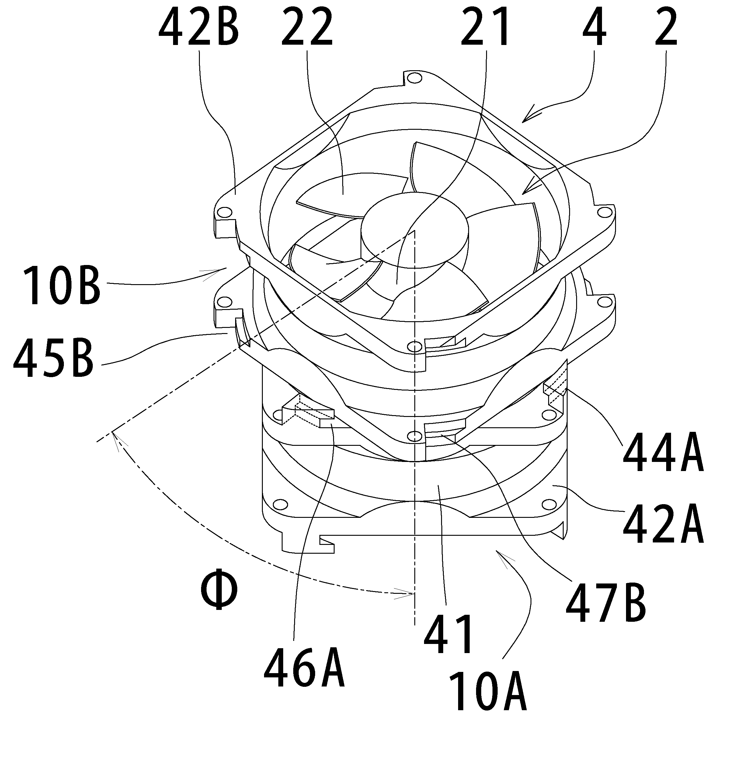
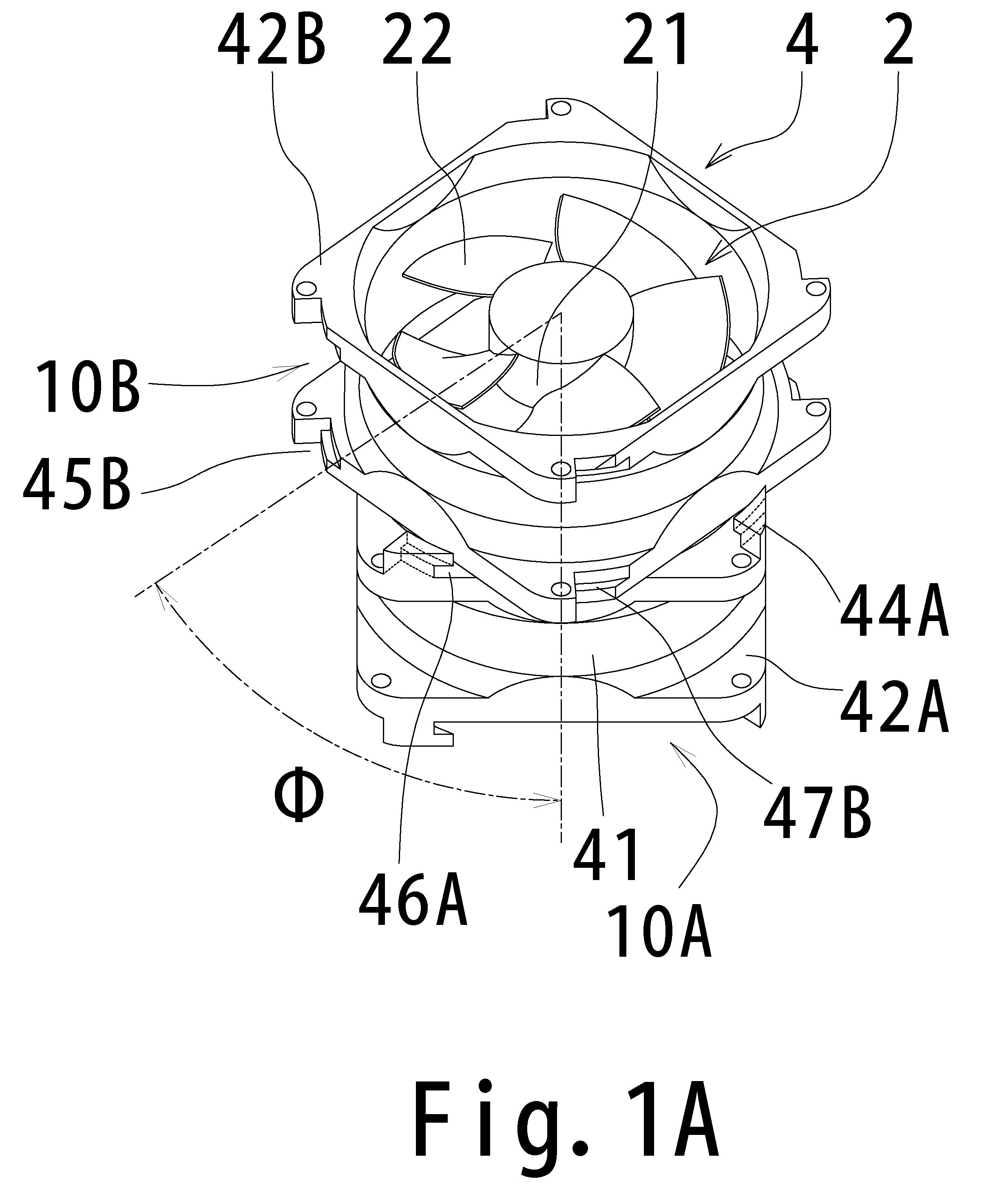
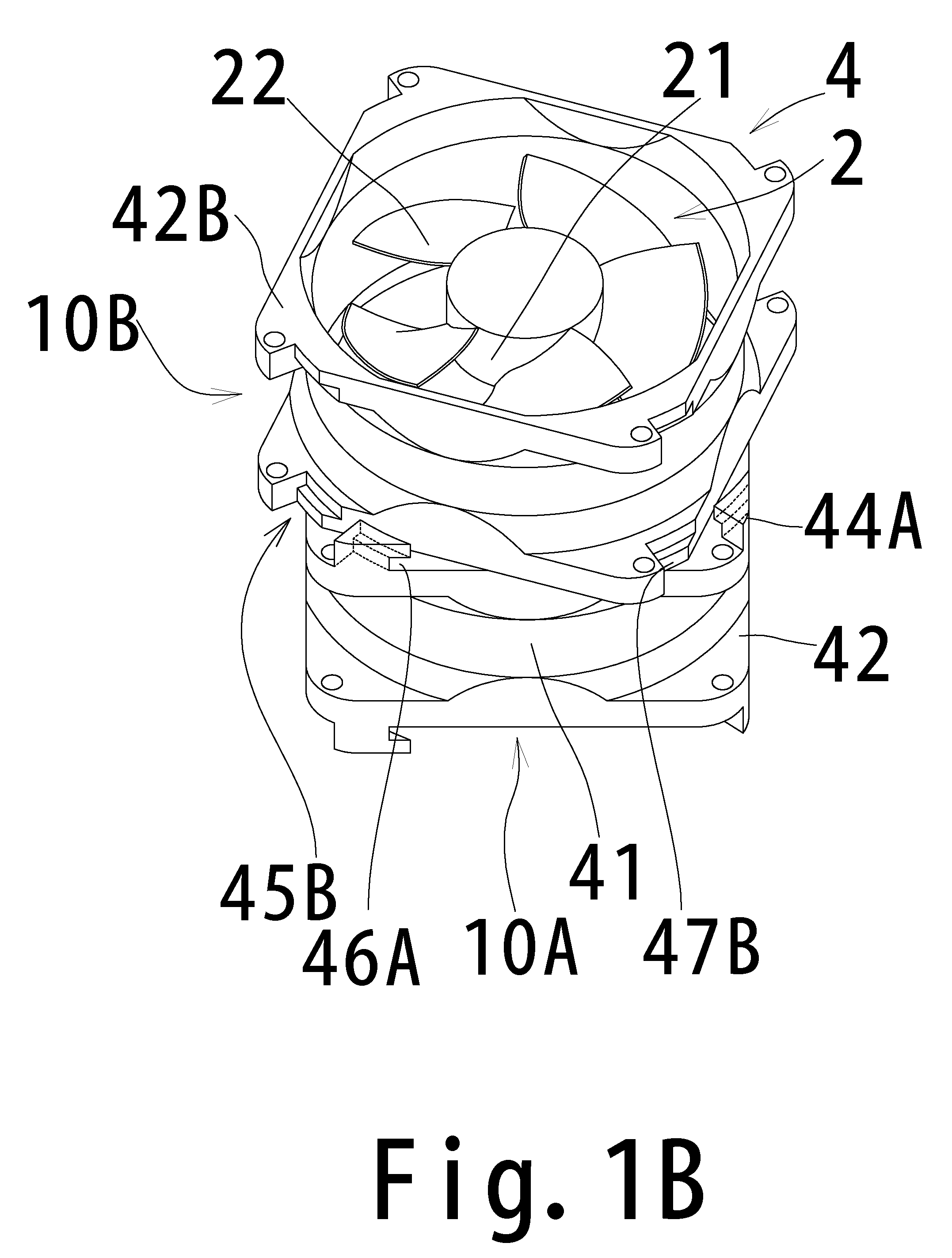
[0029]FIGS. 1A, 1B, and 1C are perspective views of a fan unit according to a first preferred embodiment of the present invention. Specifically, FIG. 1C shows the fan unit 1 of the present preferred embodiment assembled by coupling two axial fans 10A, 10B, and FIGS. 1A and 1B show the states before being coupled. FIGS. 2A and 2B are enlarged views of the coupling structure of the fan unit of the present preferred embodiment. FIGS. 3A, 3B, and 3C are top views of the fan unit of the present preferred embodiment.
Configuration of the Fan Unit
[0030]Referring to FIGS. 1A, 1B, and 1C, the fan unit 1 includes two axial fans 10A and 10B coupled to each other in series in an axial direction substantially parallel to their rotational axes.
[0031]The axial fans 10A, 10B each include a substantially cylindrical peripheral wall 21 and an impeller 2 having a plurality of blades 22 regularly arranged on the outer peripheral surface of the peripheral wall 21.
[0032]The axial fans 10A, 10B each includ...
second preferred embodiment
[0056]FIGS. 4A and 4B are perspective views of a fan unit according to a second preferred embodiment of the present invention.
Configuration of the Fan Unit
[0057]The fan unit 1B of the present preferred embodiment includes an axial fan 110A having a similar structure as the axial fan 10A of the first preferred embodiment and a stationary vane 111C having fixed blades 123 which are combined serially in the direction of the rotational axis. The stationary vane 111C includes the plurality of fixed blades 123 regularly arranged on the circumference and a housing 104C having a cylindrical portion 141C for fixing the outer peripheral ends of the fixed blades 123 on a cylindrical inner side surface 141a.
[0058]With this configuration, the static pressure characteristics of the axial fan 110A can be improved. In addition, the use of a plurality of the axial fans 110A in combination can further improve the performance of the fan unit 1B.
Housing
[0059]The housing 104C of the stationary vane 111...
third preferred embodiment
[0066]FIG. 6 is a perspective view of a fan unit 1C of the third preferred embodiment, which includes coupling axial fans 10C and 10D to each other. FIGS. 7A, 7B, and 7C are perspective views of the axial fans 10C and 10D before being coupled. FIG. 8 is an enlarged view of an essential portion of the fan unit 1C of the present preferred embodiment, i.e., the structure coupling the axial fans 10C and 10D. In FIGS. 6 through 8, like reference signs designate the same or similar components as in FIGS. 1A to 3C.
[0067]Referring to FIG. 6, the fan unit 1C includes axial fans 10C and 10D coaxially arranged with each other. In the present preferred embodiment, the axial fan 10C is arranged above the axial fan 10D, as shown in FIG. 6. The axial fans 10C and 10D are coupled in series in the axial direction.
[0068]The axial fans 10C and 10D are basically the same as the axial fans 10A and 10B of the first preferred embodiment but are different at least in the coupling structure. In the followin...
PUM
 Abstract
Description
Claims
Application Information
 - R&D
- Intellectual Property
- Life Sciences
- Materials
- Tech Scout
- Unparalleled Data Quality
- Higher Quality Content
- 60% Fewer Hallucinations
Browse by: Latest US Patents, China's latest patents, Technical Efficacy Thesaurus, Application Domain, Technology Topic, Popular Technical Reports.
© 2025 PatSnap. All rights reserved.Legal|Privacy policy|Modern Slavery Act Transparency Statement|Sitemap|About US| Contact US: help@patsnap.com