Stacked constructions for electrochemical batteries

Inactive Publication Date: 2009-01-22
G4 SYNERGETICS INC
View PDF101 Cites 42 Cited by
  • Summary
  • Abstract
  • Description
  • Claims
  • Application Information

AI Technical Summary

Benefits of technology

[0008]It is therefore an object of this invention to provide stacked

Problems solved by technology

The wound cell and prismatic cell structures suffer from high electrical resistances due to their electrical paths having to cross multiple connections and span significantly long distances to cover the complete circuit from one cell to the next in a series arrangement.
However, if the current collectors of a particular cell contacted each other or if the common electrolyte of the two MPUs in a particu

Method used


Image

  • Stacked constructions for electrochemical batteries
  • Stacked constructions for electrochemical batteries
  • Stacked constructions for electrochemical batteries

Examples


Example

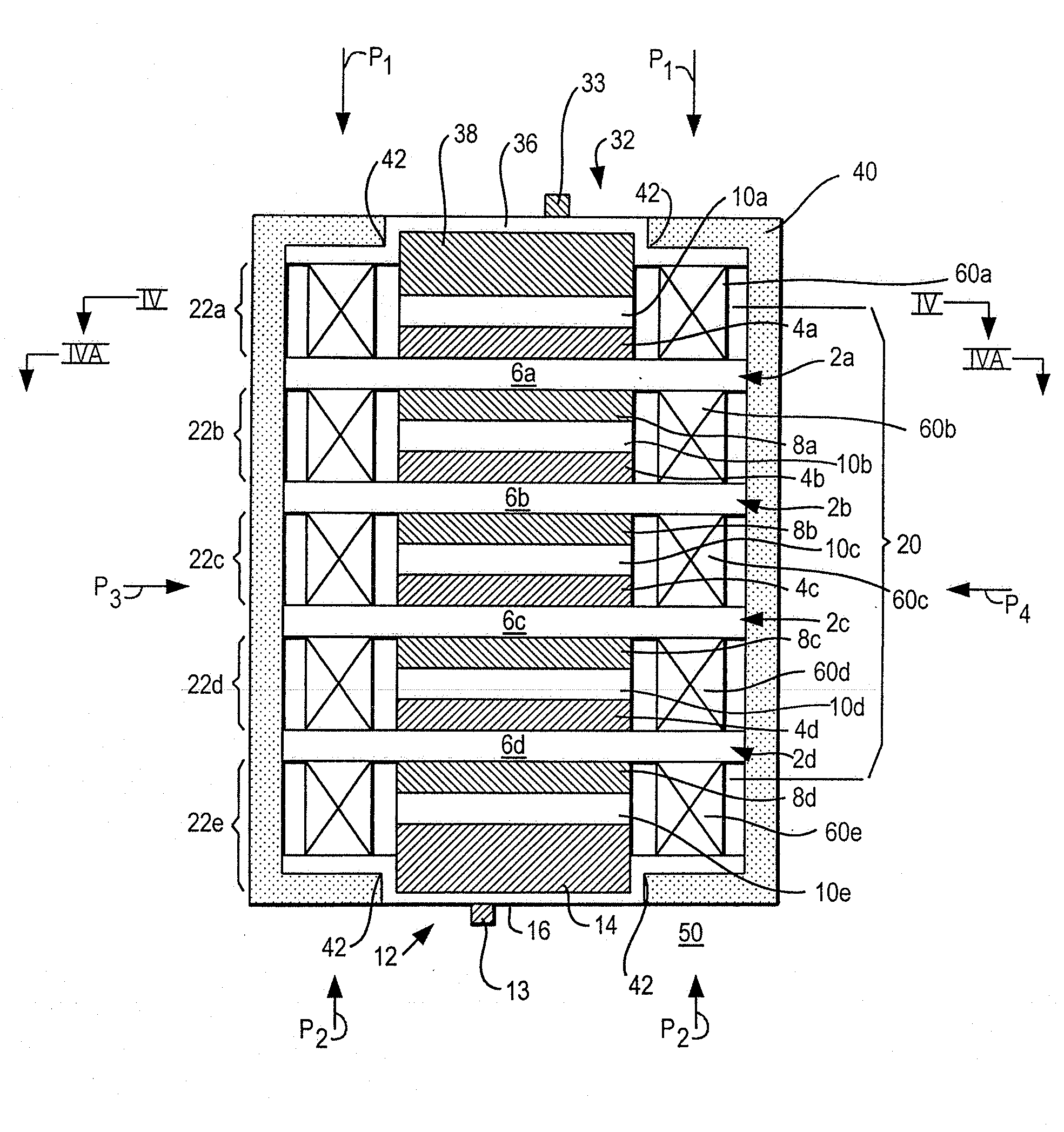
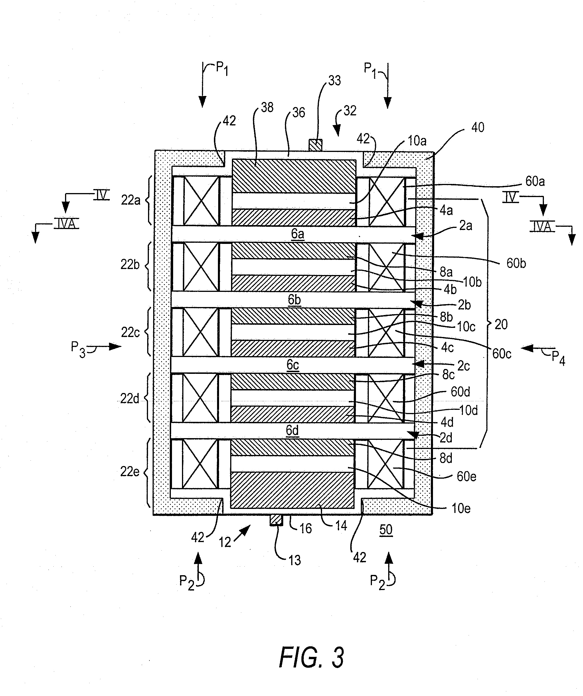
[0058]Apparatus and methods are provided for stacked batteries with improved sealing of electrolyte between adjacent cells, and are described below with reference to FIGS. 1-34B.

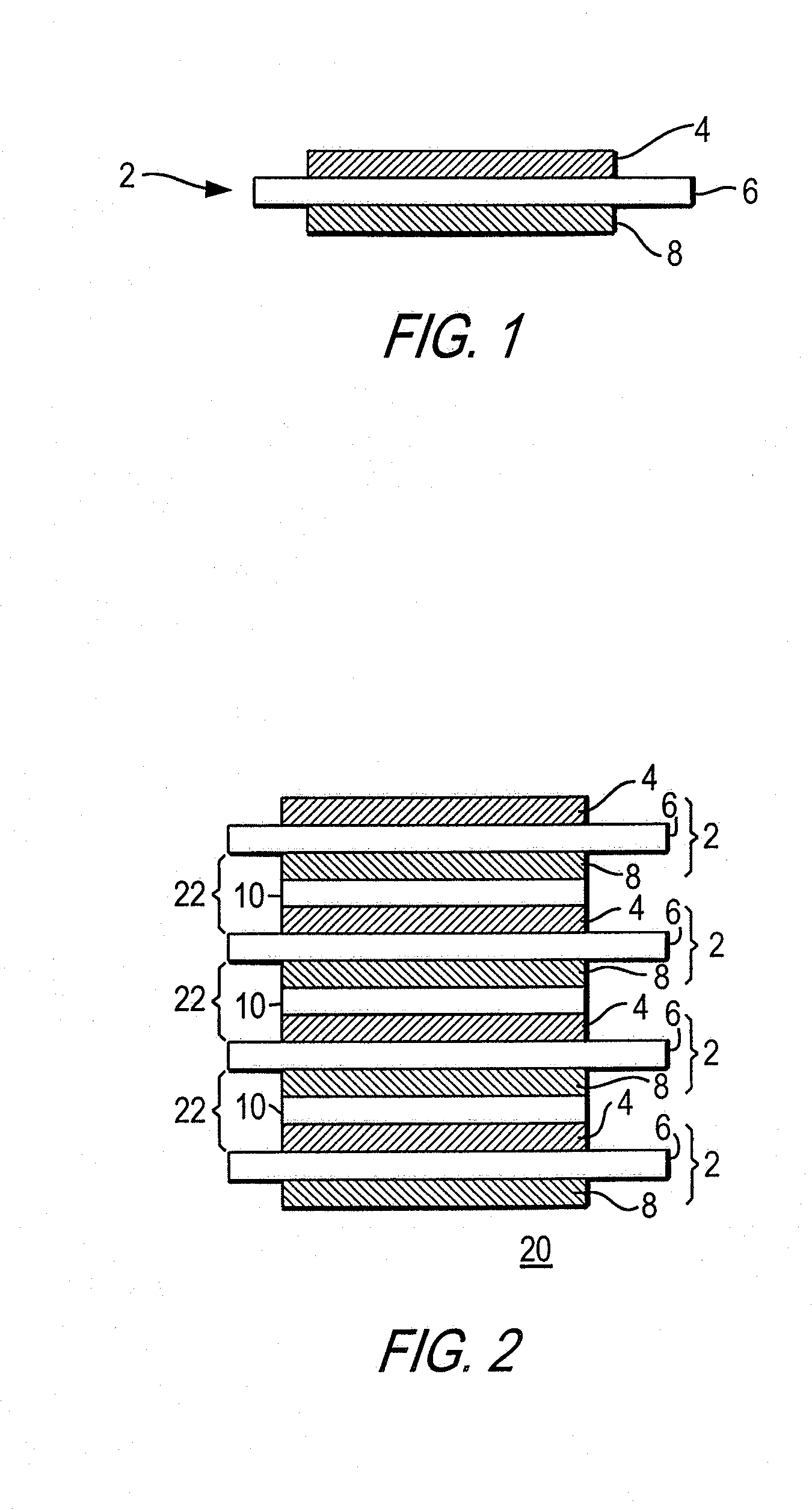
[0059]FIG. 1 shows an illustrative bi-polar unit or BPU 2, in accordance with one embodiment of the present invention. BPU 2 can include a positive active material electrode layer 4 that may be provided on a first side of an impermeable conductive substrate or current collector 6, and a negative active material electrode layer 8 that may be provided on the other side of impermeable conductive substrate 6.

[0060]As shown in FIG. 2, for example, multiple BPUs 2 may be stacked substantially vertically into a stack 20, with an electrolyte layer 10 that may be provided between two adjacent BPUs 2, such that positive electrode layer 4 of one BPU 2 may be opposed to negative electrode layer 8 of an adjacent BPU 2 via electrolyte layer 10. Each electrolyte layer 10 can include a separator 9 that may hold an electroly...


PUM


Abstract

A stacked battery has at least two cell segments arranged in a stack. Each cell segment may have a first electrode unit having a first active material electrode, a second electrode unit having a second active material electrode, and an electrolyte layer between the active material electrodes. One or more gaskets may be included in each cell segment to seal the electrolyte within the cell segment.

Description

[0001]This application claims the benefit of U.S. Provisional Patent Application No. 60 / 901,046, filed Feb. 12, 2007, which is hereby incorporated by reference herein in its entirety.FIELD OF THE INVENTION[0002]This invention can relate generally to batteries and, more particularly, to apparatus and methods for improving the stacked constructions of electrochemical batteries.BACKGROUND OF THE INVENTION[0003]Conventional batteries have been manufactured as either a wound cell battery that has only two electrodes or a standard prismatic cell battery that has many plate sets in parallel. In both of these types, the electrolyte can be shared everywhere within the battery. The wound cell and prismatic cell structures suffer from high electrical resistances due to their electrical paths having to cross multiple connections and span significantly long distances to cover the complete circuit from one cell to the next in a series arrangement.[0004]Recently, various types of batteries with se...

Claims


Application Information

Patent Timeline
IPC IPC(8): H01M6/46H01M50/186
CPCH01M2/08H01M6/42H01M10/0468H01M10/0418H01M10/0413H01M10/04H01M50/186Y02E60/10Y02P70/50H01M2220/20H01M6/46
Inventor OGG, RANDYHIGGINS, MARTIN PATRICK
Owner G4 SYNERGETICS INC
Why Eureka
Try Eureka