
Panel

a technology of composite cladding and panels, applied in the field of composite cladding panels, can solve the problem that panels can be often uninteresting aesthetically

Inactive Publication Date: 2009-01-29
KINGSPAN HLDG (IRL) LTD
View PDF12 Cites 36 Cited by
  • Summary
  • Abstract
  • Description
  • Claims
  • Application Information

AI Technical Summary

Benefits of technology

[0002]Buildings comprising a steel frame on which pre-formed panels are mounted may be erected quickly and more cheaply than buildings with brick or block facades.

Problems solved by technology

One of the problems with buildings constructed from pre-formed panels is that such panels can often be uninteresting aesthetically.

Method used


Image

  • Panel
  • Panel
  • Panel

Examples


Embodiment Construction

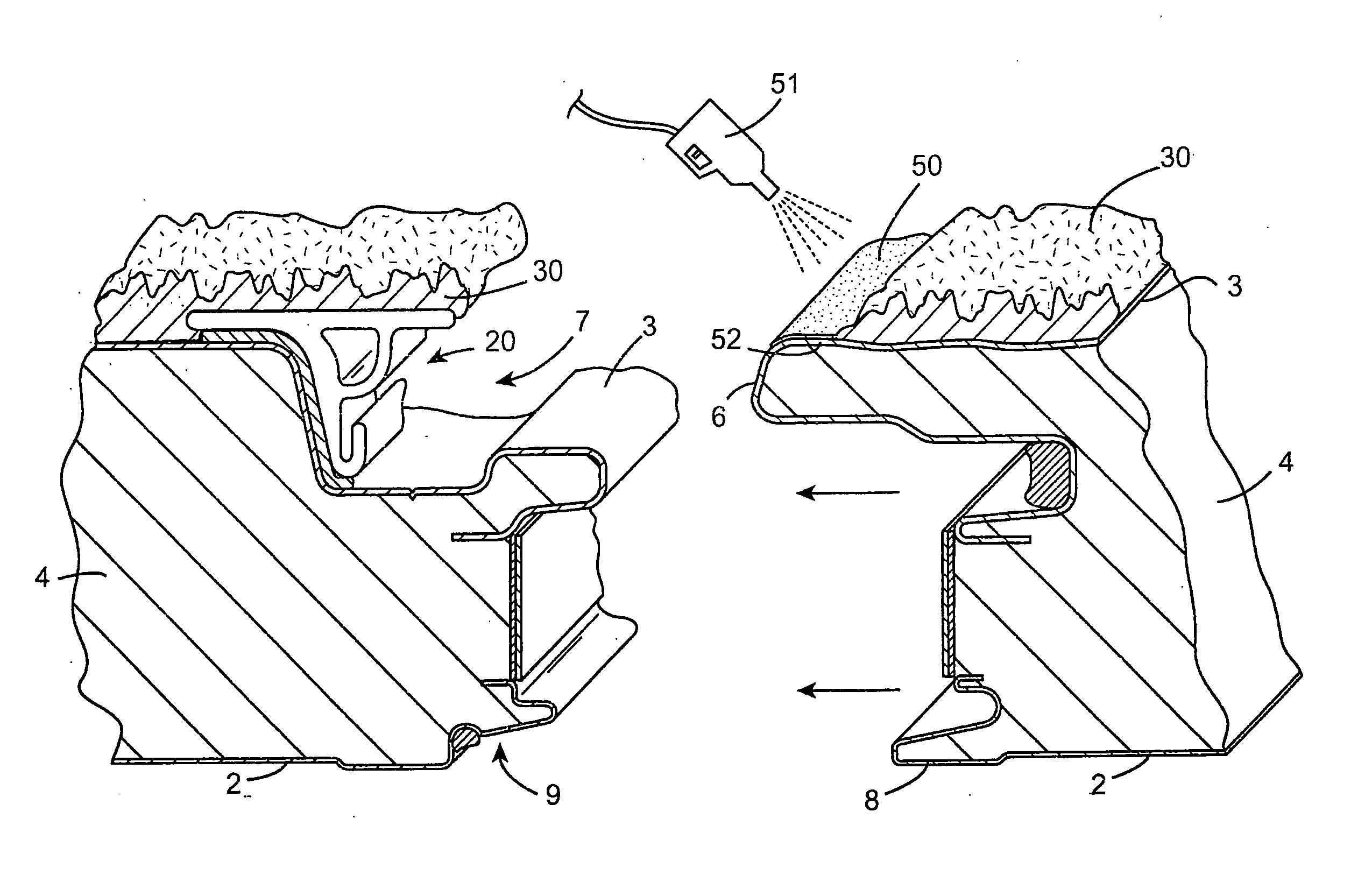
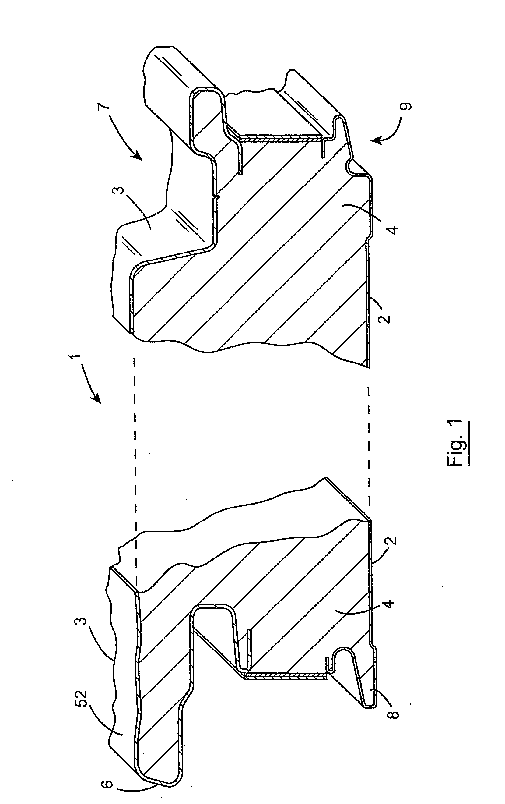
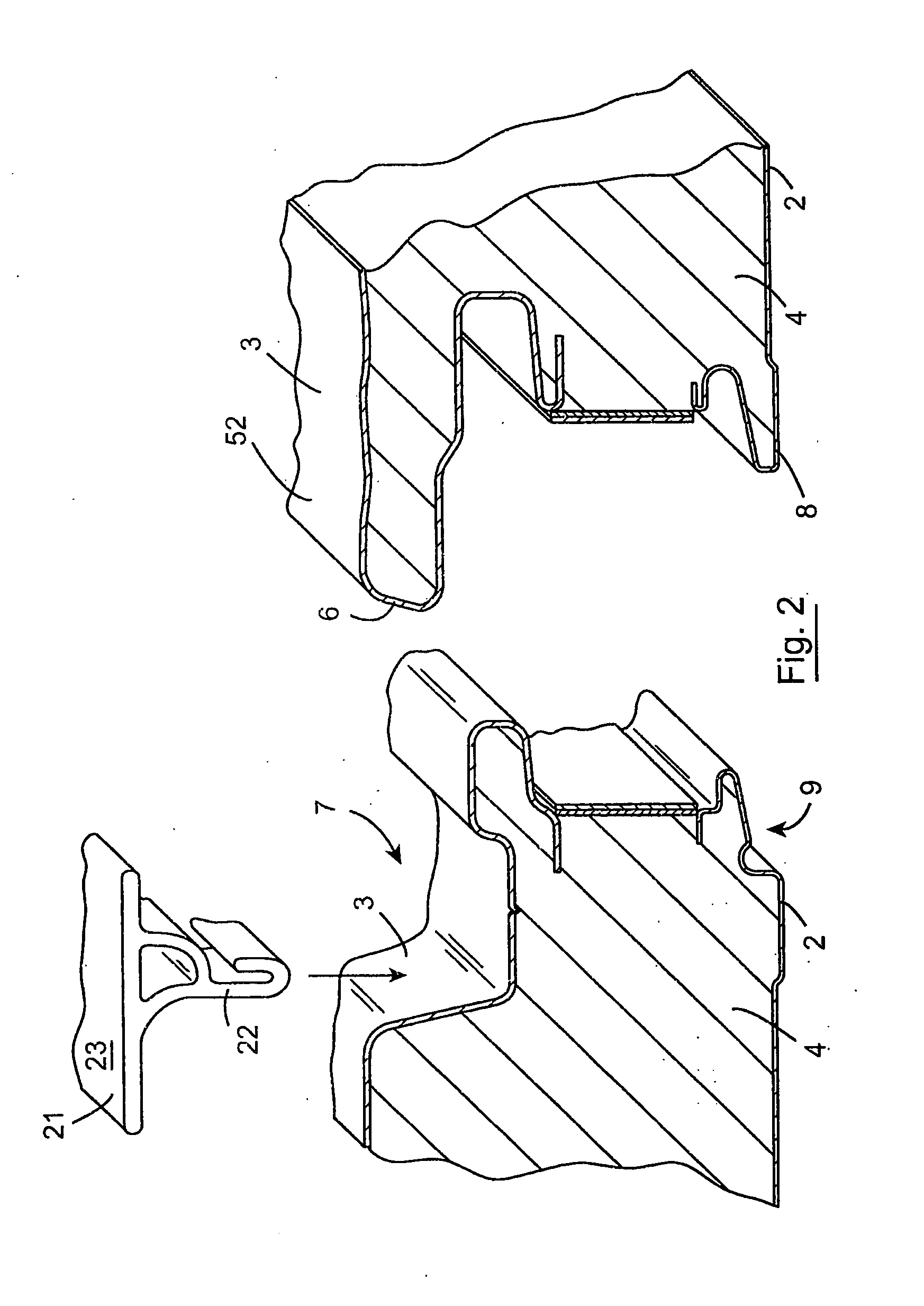
[0023]Referring to the drawings and initially to FIG. 1 there is illustrated a composite cladding panel 1. The panel 1 comprises a skin or backing tray 2 which is usually of steel and an external skin 3 which is also usually of steel with a layer of foam insulation material 4 such as a phenolic or polyurethane based foam material therebetween. The panel may be of any suitable type such as that described in our UK 2325678A.

[0024]The panel has formations along both side edges. The formations are profiled so that one side edge of a panel is interengagable, on assembly, with the opposite side edge of an adjacent panel. Thus, the external skin 3 is profiled to define a male projecting part 6 along one side and a corresponding recess 7 along the opposite side. Similarly the internal skin 2 is profiled to define a male projecting part 8 along one side and a corresponding recess 9 along the opposite side. Various seals may be provided at the joint.

[0025]In the invention, a pre-formed gasket...


PUM


Abstract

A composite cladding panel has an internal skin or backing tray (2), and an external skin (3) with foam insulation (4) between the tray (2) and skin (3). A pre-formed gasket (20) is bonded to the external skin (3) and a coating (30) is applied to the external skin (3) of the panel and to an outer face (21) of the gasket (20) to provide a surface finish such as a textured finish. No joint is visible between the coated skins (3) of adjacent panels.

Description

INTRODUCTION[0001]The invention relates to a composite cladding panel of the type comprising an inner skin and an external skin with insulation foam material therebetween.[0002]Buildings comprising a steel frame on which pre-formed panels are mounted may be erected quickly and more cheaply than buildings with brick or block facades.[0003]One of the problems with buildings constructed from pre-formed panels is that such panels can often be uninteresting aesthetically. It is known to form such panels with various profiles and in various colours, however, there is still a need to provide an aesthetically different façade in some cases.[0004]This invention is directed towards providing a panel system which will address this need.STATEMENTS OF INVENTION[0005]According to the invention there is provided a composite cladding panel comprising an internal skin and an external skin with insulation material therebetween, one of the skins having a gasket extending along one edge thereof, the ga...

Claims


Application Information

Patent Timeline
Patent Type & Authority Applications(United States)
IPC IPC(8): E04F13/08E04C2/284
CPCE04C2/292E04F13/0876E04F13/042E04F21/12E04F2201/07E04F13/0889E04D3/352E04D3/355E04C2/526E04D3/38
Inventor FLYNN, GREGORYCAROLAN, JAMES
Owner KINGSPAN HLDG (IRL) LTD
Learn More