Suppression of higher-order modes by resonant coupling in bend-compensated optical fibers

a technology of resonant coupling and optical fiber, which is applied in the field of higher-order mode suppression in optical fibers, can solve the problems of neglecting the impact of bending the fiber on index-matched coupling and frustrating the intended effect, and achieve the effect of suppressing homs

Active Publication Date: 2009-02-05
OFS FITEL LLC
View PDF4 Cites 60 Cited by
  • Summary
  • Abstract
  • Description
  • Claims
  • Application Information

AI Technical Summary

Benefits of technology

[0014]In effect, the pedestal regions are configured so that the fiber is pre-compensated for the bend effect described above; that is, an uncompensated bent fiber segment suffers high fundamental mode loss due to resonant coupling, whereas the pre-compensated bent fiber segment selectively couples any unwanted HOM from the core region into the pedestal region.

Problems solved by technology

However, in this simple analysis the impact of bending the fiber on index-matched coupling has been neglected.
Consequently, the bent fiber 10′ may frustrate the intended result.

Method used


Image

  • Suppression of higher-order modes by resonant coupling in bend-compensated optical fibers
  • Suppression of higher-order modes by resonant coupling in bend-compensated optical fibers
  • Suppression of higher-order modes by resonant coupling in bend-compensated optical fibers

Examples


Embodiment Construction

Optical Fiber Design—General Considerations

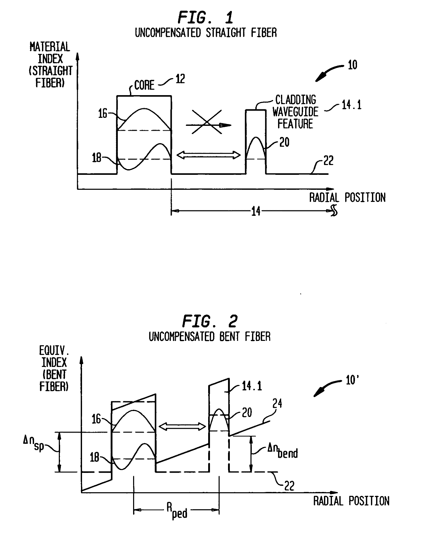
[0033]The first consideration in pre-compensating fibers in accordance with my invention is to understand when the bend in a fiber, or fiber segment, is sufficiently large to have a significant impact on fiber performance. Thus, returning to FIG. 2, when fiber 10′ is bent to a radius Rbend, the index profile at the center of feature 14.1 increases by an amount Δnbend, but the effective index difference (or spacing) Δnsp of modes 16, 18 remains relatively constant because both modes are centered in the core region. The issue to be addressed is this: When is Rbend so small that selective resonant coupling is disrupted? More specifically, when is Rbend so small that resonant coupling between (i) unwanted HOM 18 and feature mode 20 is disrupted and (ii) fundamental mode 16 and feature mode 20 (or any other mode of feature 14.1) is undesirably introduced? My analysis indicates that Rbend is too small when Δnbend is comparable to Δnsp, as shown i...


PUM


Abstract

The effect of bending is anticipated in an optical fiber design, so that resonant coupling remains an effective strategy for suppressing HOMs. The index profile of the fiber and its bend radius are configured so that there is selective resonant coupling of at least one HOM, but not the fundamental mode, in the bent segment of the fiber. In an illustrative embodiment, the bend radius (or predetermined range of bend radii) of an optical fiber is known a priori. The core and cladding regions are configured to support (guide) the propagation of signal light in a fundamental transverse mode and at least one higher-order transverse mode in the core region. The cladding region includes an outer cladding region and an annular trench region. The trench region includes at least one axially extending, raised-index pedestal (waveguide) region having a refractive index higher than that of the outer cladding region. Within at least the bent segment the at least one pedestal region is configured (i) to support the propagation of at least one transverse mode and (ii) to resonantly couple at least one of the higher-order transverse modes (HOMs) of the core region to at least one transverse mode (e.g., the fundamental mode) of the pedestal region when the fiber is bent to a radius within the predetermined range of radii. In effect, the pedestal regions are configured so that the fiber is pre-compensated for the effect of bending; that is, an uncompensated bent fiber segment suffers high fundamental mode loss due to resonant coupling, whereas the pre-compensated bent fiber segment selectively couples any unwanted HOM from the core region into the pedestal region. In a preferred embodiment, the optical fiber is a LMA fiber incorporated in an optical fiber amplifier or laser package.

Description

CROSS-REFERENCE TO RELATED APPLICATIONS[0001]This application claims priority from provisional application Ser. No. 60 / 950,618, which was filed on Jul. 19, 2007 and is entitled “Large-Mode-Area Fiber Design with Suppression of Higher-Order Modes.”[0002]This application is also a continuation-in-part of application Ser. No. 11 / 319,121 (Fini 2), which was filed on Dec. 27, 2005 and is entitled “Optical Fiber with Specialized Index Profile to Compensate for Bend-Induced Distortion.”GOVERNMENT CONTRACT[0003]This invention was made with Government support under the Advanced Technology Program of the National Institute of Standards and Technology, Award No. 70NANB4H3035. The Government has certain rights in this invention.BACKGROUND OF THE INVENTION[0004]1. Field of the Invention[0005]This invention relates to mode suppression in optical fibers and, more particularly, to the suppression of higher-order modes by resonant coupling in bend-compensated fibers, including, for example, large-mo...

Claims


Application Information

Patent Timeline
Patent Type & Authority Applications(United States)
IPC IPC(8): H01S3/00G02B6/036
CPCG02B6/02019G02B6/02023G02B6/02366G02B6/03644H01S3/06729G02B6/03688G02B6/03694G02B6/14H01S3/06708G02B6/03666
Inventor FINI, JOHN MICHAEL
Owner OFS FITEL LLC
Why Eureka
Try Eureka