
Fan apparatus

Active Publication Date: 2009-02-12
NIDEC CORP
View PDF9 Cites 15 Cited by
  • Summary
  • Abstract
  • Description
  • Claims
  • Application Information

AI Technical Summary

Benefits of technology

[0009]Other features, elements, advantages and characteristics of the present invention will become more apparent

Problems solved by technology

For this reason, heat generated by the electronic components (e.g., MPU, memories, and the like) disposed in the respective blades is undesirably likely to stay inside the enclosure.

Method used


Image

  • Fan apparatus
  • Fan apparatus
  • Fan apparatus

Examples


Embodiment Construction

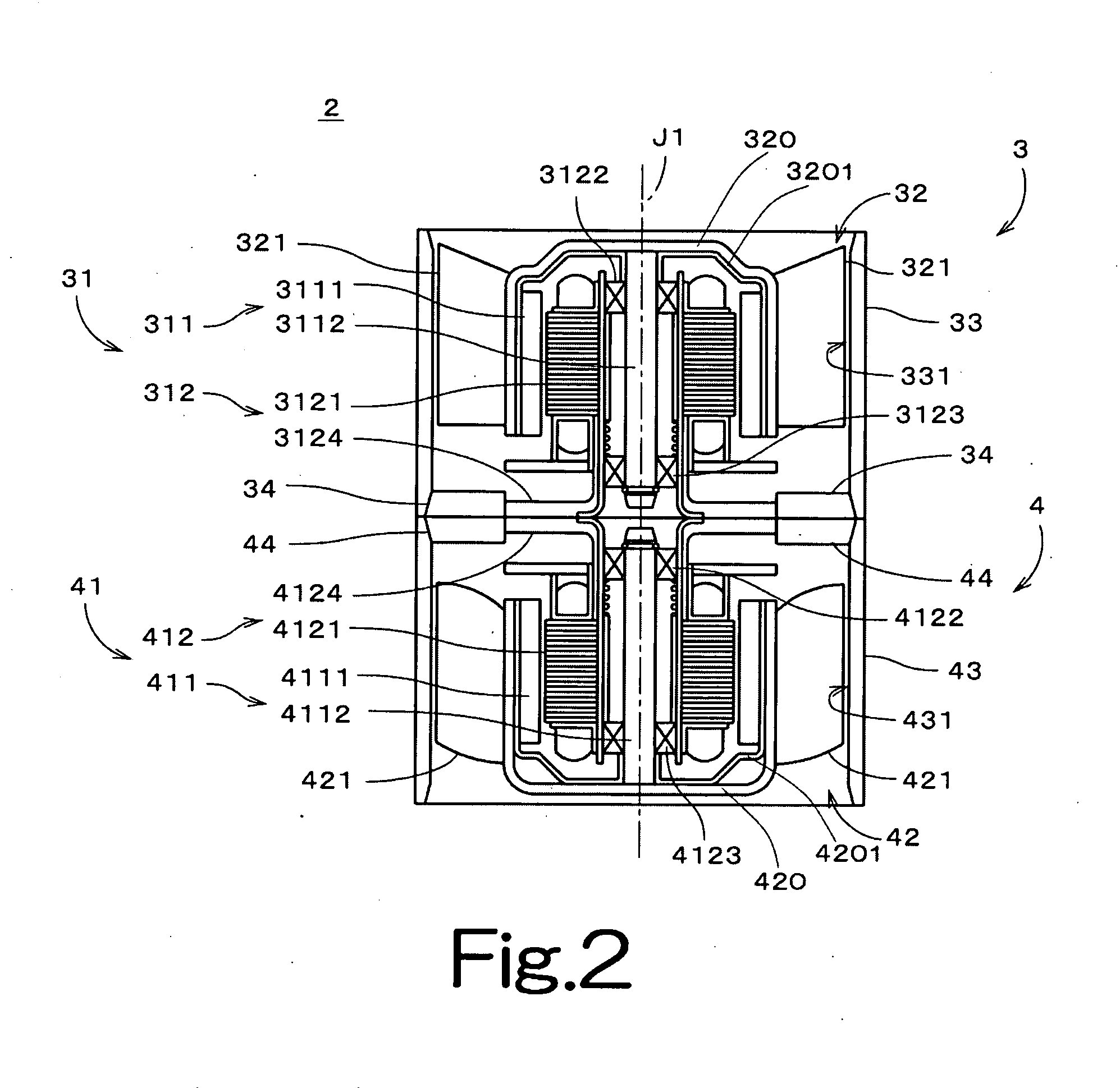
[0032]Referring to FIGS. 1 through 22, preferred embodiments of the present invention will be described in detail. It should be noted that in the explanation of the preferred embodiments of the present invention, when positional relationships among and orientations of the different components are described as being up / down or left / right, ultimately positional relationships and orientations that are in the drawings are indicated, positional relationships among and orientations of the components once having been assembled into an actual device are not indicated. In the following description, an axial direction indicates a direction substantially parallel to a rotation axis, and a radial direction indicates a direction substantially perpendicular to the rotation axis.

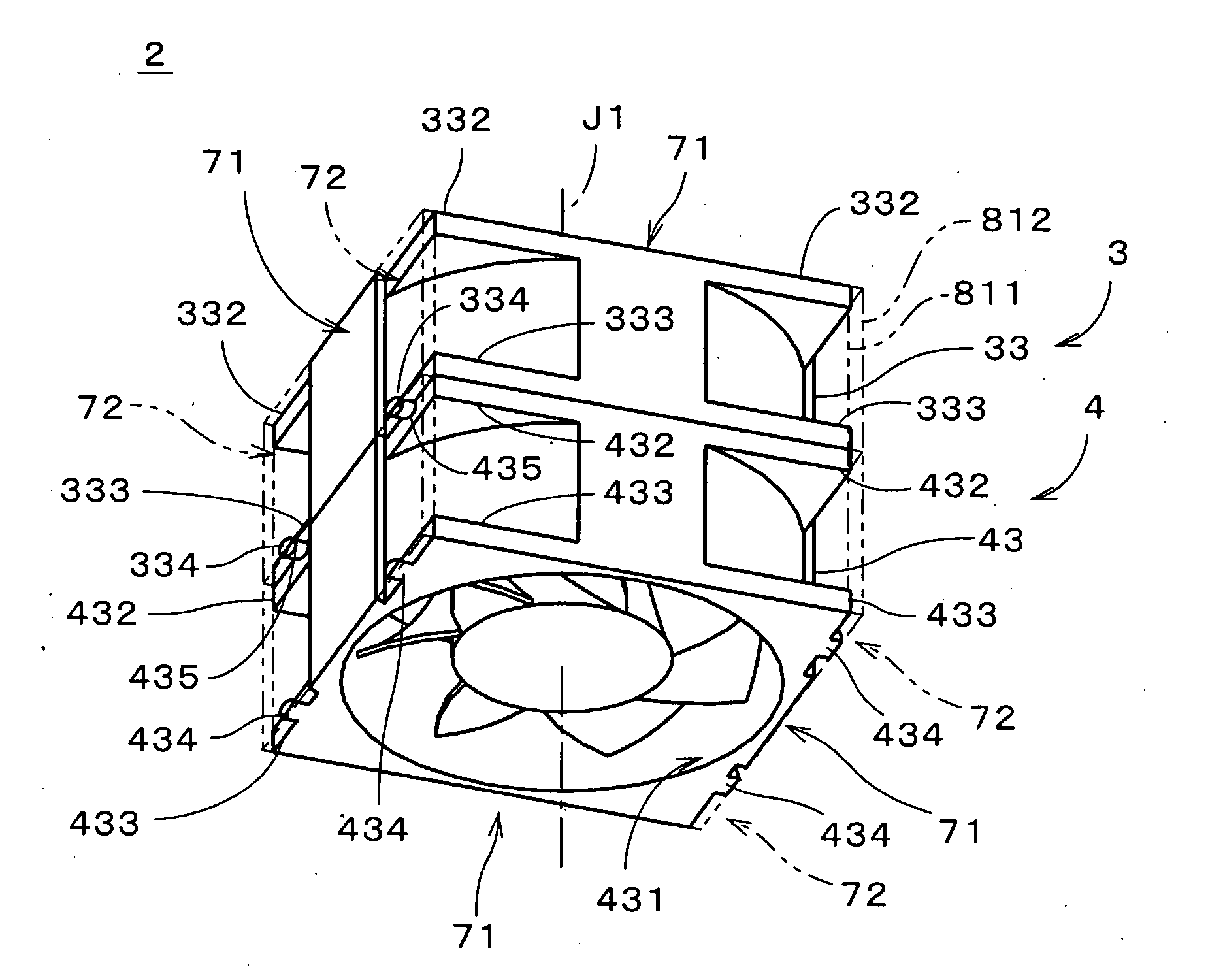
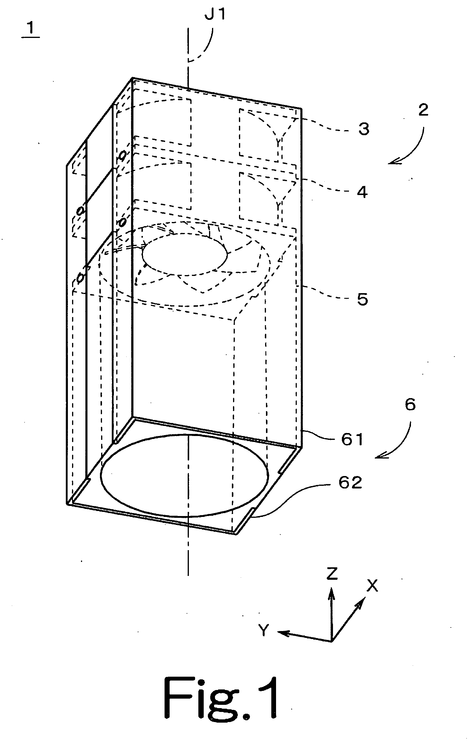
[0033]FIG. 1 is a perspective view of a fan apparatus 1 of the first preferred embodiment of the present invention. In FIG. 1, the inner structure of the fan apparatus 1 is depicted by dashed lines.

[0034]The fan apparatus ...


PUM


Abstract

A fan apparatus includes a fan section having a hollow housing with an inlet and an outlet, and a hollow duct section disposed on the outlet side of the fan section. The housing and the duct section are coupled by a coupling member.

Description

BACKGROUND OF THE INVENTION[0001]1. Field of the Invention[0002]The present invention relates to a fan apparatus.[0003]2. Description of the Related Art[0004]A server computer has a function of transmitting information to client computers. Such server computers may include a rack-mount server and a blade server, for example.[0005]Generally, a blade server is provided with a plurality of plate-like blades, an enclosure, and a rack. Each blade includes an MPU (Micro Processing Unit), memories, and the like mounted thereon. The blades are accommodated in the enclosure using a high density arrangement, and are attached to the rack for storage together with the enclosure. In general, a power supply for supplying a current to the blade server and a cooling device for cooling the blade server are shared by a plurality of blades disposed in one enclosure.[0006]As described above, the cooling device is disposed in the inside of the enclosure. In the enclosure, a plurality of blades are dispo...

Claims


Application Information

Patent Timeline
IPC IPC(8): G06F1/20H05K7/20
CPCH05K7/20172G06F1/20F04D19/007F04D29/646
Inventor YAMADA, SUGURUNISHIDA, HIRONOBUHAYASHIGAITO, TOMOIWAMOTO, KENJI
Owner NIDEC CORP
Features
  • Generate Ideas
  • Intellectual Property
  • Life Sciences
  • Materials
  • Tech Scout
  • Unparalleled Data Quality
  • Higher Quality Content
  • 60% Fewer Hallucinations
Learn More