Orthodontic appliance

Inactive Publication Date: 2009-02-12
PHC HLDG CORP
View PDF10 Cites 36 Cited by
  • Summary
  • Abstract
  • Description
  • Claims
  • Application Information

AI Technical Summary

Benefits of technology

[0013]In order to solve the above problems, an object of the present invention is to provide an orthodontic appliance capable of efficiently applying vibration to teeth to be aligned and enabling a treatment to be easily and safely continued even at home.
[0014]In order to accomplish the above object, an orthodontic appliance according to the present invention comprises a load applying mechanism and a vibration generating actuator. The load applying mechanism is mounted on teeth to apply a load for teeth alignment to a specified tooth in the teeth. The vibration generating actuator includes a contact portion that i

Problems solved by technology

However, the teeth alignment using the orthodontic wire takes a very long time (fastest six months, normally several years) until an orthodontic treatment is finished.
Such a long treatment period increases burdens on patients, causing them to give up easily.
However, the appliances disclosed in the above Patent Literatures 1, 2 have a problem that ultrasonic vibration cannot be efficiently applied to the teeth to be aligned since

Method used


Image

  • Orthodontic appliance
  • Orthodontic appliance
  • Orthodontic appliance

Examples


first embodiment

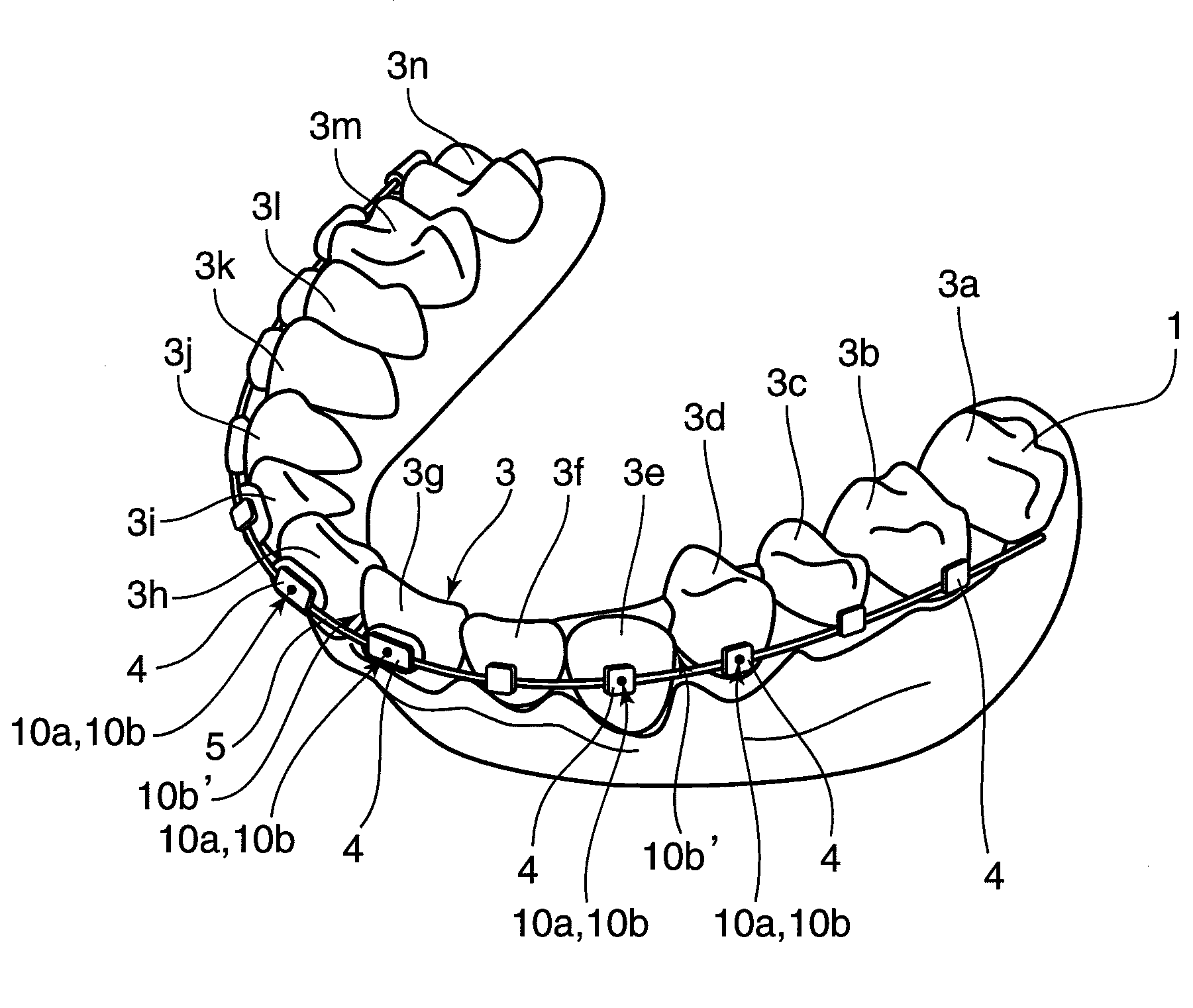
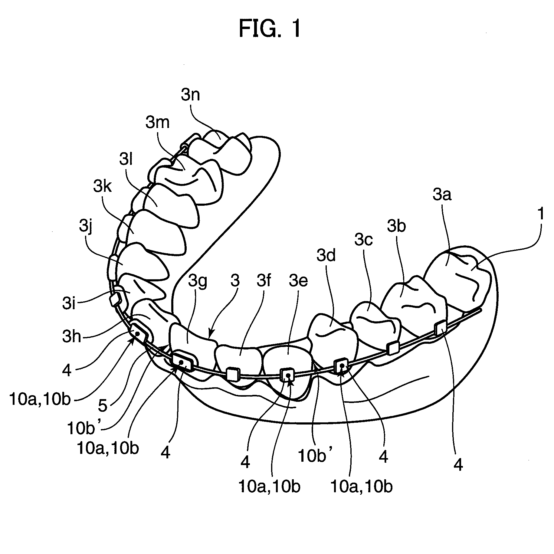
[0023]FIG. 1 is a perspective view of a dental cast 1 of a lower dental arch according to the present invention. This dental cast 1 has a teeth group 3 that includes a plurality of teeth 3a to 3n, wherein the teeth 3a, 3n are posterior teeth. A load applying mechanism for teeth alignment is mounted on the teeth 3b to 3m excluding these posterior teeth.

[0024]This load applying mechanism includes a plurality of brackets 4 to be fixed to the buccal surfaces of the teeth 3b to 3m and an orthodontic wire (arch wire) 5 arranged to connect these brackets 4. This orthodontic wire 5 is latched to the teeth 3b to 3m by the respective brackets 4. The orthodontic wire 5 is elastically deformably latched, so that an elastic restoring force thereof acts as a constant static load on the teeth group 3. The application of this static load corrects malocclusion. It should be noted that the load applying mechanism for aligning the teeth is not limited to the one shown in FIG. 1.

[0025]An orthodontic ap...

second embodiment

[0037]the present invention is shown in FIGS. 4 and 5. A load applying mechanism according to this embodiment is constructed by a dental mouthpiece 9 and projections 15, and this load applying mechanism applies constant forces (static loads) to teeth 3d, 3e, 3g and 3h to be aligned.

[0038]As shown in FIG. 5A, each projection 15 is so fixed to the front surface of a corresponding one of the teeth 3d, 3e, 3g and 3h to be aligned of a teeth group 3 as to project forward. The dental mouthpiece 9 is fitted over these projections 15 as shown in FIGS. 4 and 5B, and forcibly mounted on the teeth group 3. This mounted dental mouthpiece 9 comes to possess contraction forces, which concentrate on the projections 15. The forces concentrated on the projections 15 are applied to the teeth 3d, 3e, 3g and 3h to be aligned as constant forces (arrow “a”) for teeth alignment.

[0039]A material for ordinary mouthpieces (or mouth guards) and having guaranteed hygienic safety is normally used as the materia...


PUM


Abstract

The present invention aims to provide an orthodontic appliance capable of efficiently applying vibration to teeth to be aligned and enabling a treatment to be easily and safely continued even at home. This appliance is provided with a load applying mechanism and a vibration generating actuator. The load applying mechanism is mounted on teeth to apply a load for the malocclusion correction to a specified tooth in the teeth. The vibration generating actuator includes a contact portion that is inserted into a buccal cavity containing the teeth and can come into contact with a part of the load applying mechanism corresponding to the specified tooth or the specified tooth, and applies a vibration force from the contact portion to the specified tooth or the part of the load applying mechanism.

Description

TECHNICAL FIELD[0001]The present invention relates to an orthodontic appliance.BACKGROUND ART[0002]An orthodontic appliance equipped with an orthodontic wire to be mounted on teeth has been conventionally known. An elastic restoring force of the orthodontic wire acts as a constant static load on the teeth to correct teeth malalignment or crossbite. In other words, the orthodontic appliance is based on the principle of aligning the teeth by gradually deforming an alveolar bone supporting the teeth in the gum (bone reconstruction, bone remodeling) through the application of a constant force to the teeth.[0003]However, the teeth alignment using the orthodontic wire takes a very long time (fastest six months, normally several years) until an orthodontic treatment is finished. Such a long treatment period increases burdens on patients, causing them to give up easily.[0004]In order to shorten a period of such an orthodontic treatment, technology of giving a vibration force to the teeth ha...

Claims


Application Information

Patent Timeline
IPC IPC(8): A61C7/00
CPCA61C7/00A61C7/08A61C7/008
Inventor YAMAMOTO, TERUKOKAMIOKA, HIROSHIADACHI, TAIJIFUKUSHIMA, SHOGOSAKIMURA, TAKUMI
Owner PHC HLDG CORP
Why Eureka
Try Eureka