
Method, apparatus and computer program product for facilitating data entry using an offset connection element

a technology of offset connection element and data entry method, which is applied in the field of electronic device touchscreens, can solve the problems of increasing screen size, difficult if not impossible for users to be certain which items to use, and the use of the display screen as a touch sensitive input device has become somewhat difficul

Inactive Publication Date: 2009-02-12
NOKIA CORP
View PDF31 Cites 28 Cited by
  • Summary
  • Abstract
  • Description
  • Claims
  • Application Information

AI Technical Summary

Benefits of technology

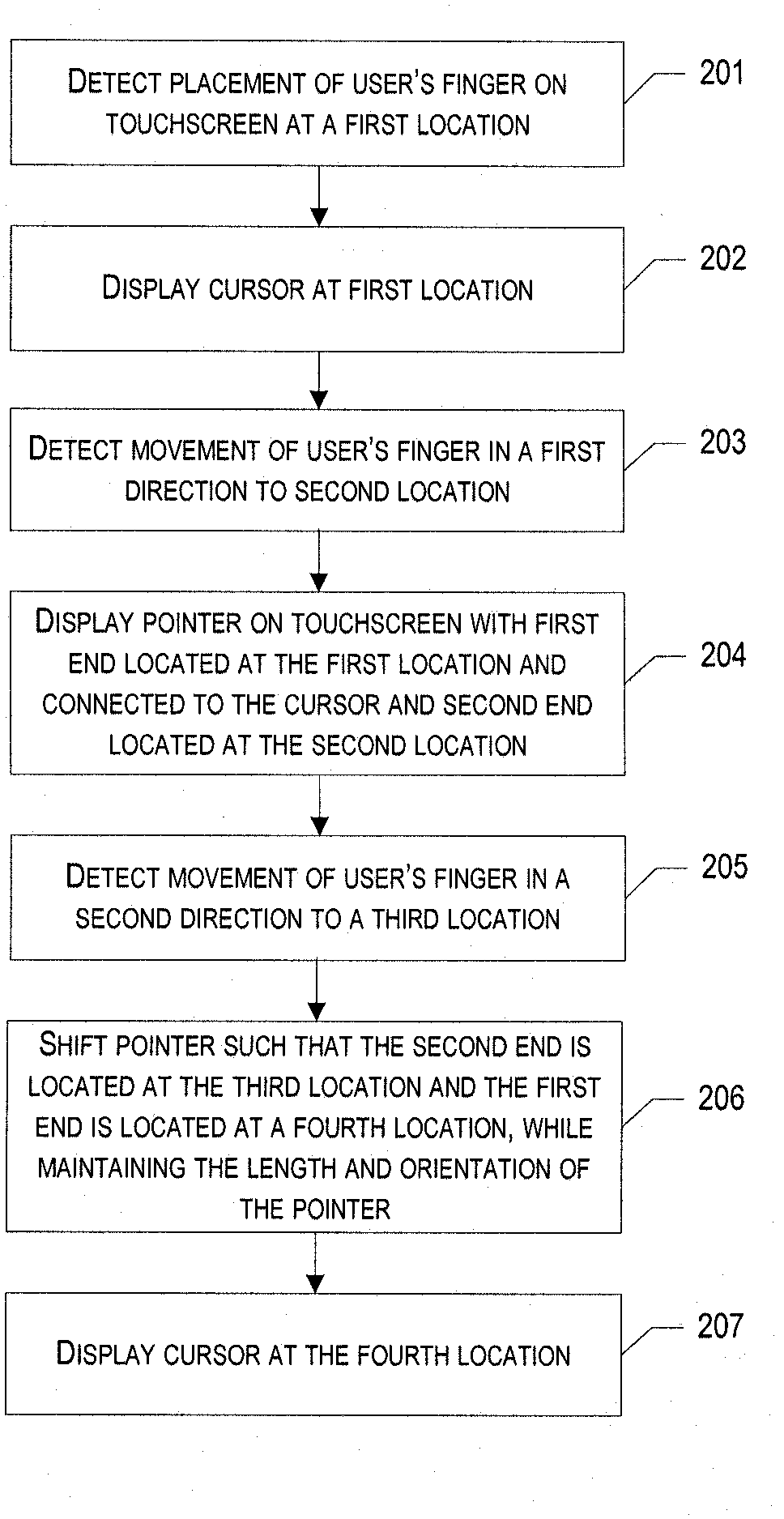
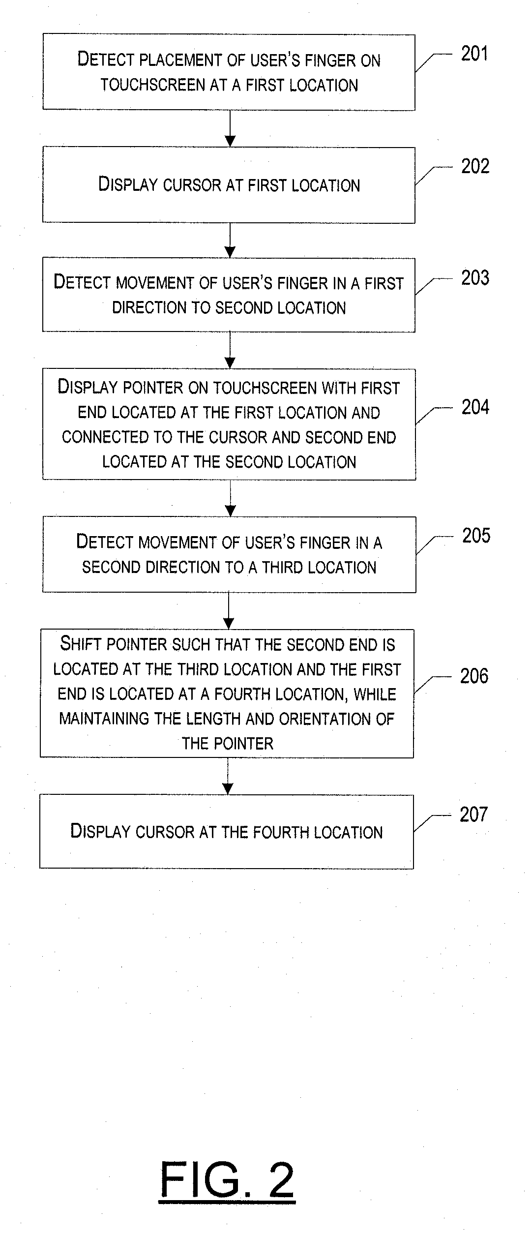
[0012]In accordance with one aspect, a method is provided of facilitating data entry using an offset connection element, such as a pointer. In one exemplary embodiment, the method may include: (1) detecting a tactile input from a user at a first location on a touch sensitive input device; (2) causing a display of a cursor at the first location on the touch sensitive input device; (3) receiving an indication of a movement of the tactile input in a first direction to a second location on the touch sensitive input device; (4) causing, in response, a display of a connection element on the touch sensitive input device that extends at least partially between the first location and the second location; and (5) enabling the user to manipulate the display of the cursor through manipulation of the connection element.
[0013]In one exemplary embodiment, enabling the user to manipulate the display of the cursor through manipulation of the connection element may further comprise: receiving an indication of a movement of the tactile input in a second direction different from the first direction to a third location on the touch sensitive input device; translating the connection element displayed on the touch sensitive input device such that the connection element extends at least partially between the third location and a fourth location, wherein the angle and distance between the third and fourth locations are substantially the same as that between the first and second locations; and causing a display of the cursor at the fourth location.
[0016]According to another aspect, apparatus is provided for facilitating data entry using an offset pointer. In one exemplary embodiment the apparatus includes: (1) means for detecting a tactile input from a user at a first location on a touch sensitive input device; (2) means for causing a display of a cursor at the first location on the touch sensitive input device; (3) means for receiving an indication of a movement of the tactile input in a first direction to a second location on the touch sensitive input device; (4) means for causing, in response, a display of a connection element on the touch sensitive input device that extends at least partially between the first location and the second location; and (5) means for enabling the user to manipulate the display of the cursor through manipulation of the connection element.

Problems solved by technology

However, because the display screens appear to be getting smaller over time, use of the display screen as a touch sensitive input device has become somewhat difficult.
Consequently, it is difficult if not impossible for the user to be certain which item he or she is selecting.
Each of these solutions, however, has at least one drawback.
One drawback of this solution is that it may be difficult to implement where selectable items were scattered throughout a touchscreen, rather than in a single row or column.
In particular, where the item the user wishes to select is surrounded by other selectable items, as the cursor moves closer to the intended item, one of the surrounding items would likely become magnified, thereby potentially making it difficult, if not impossible, to see and select the intended item.
This solution, however, requires additional steps and may further make operating the electronic device to input data a two-handed operation, which is less than ideal.
According to this solution, however, the magnified window moves with the cursor and may cause the magnified view to appear unstable, restless and wobbly.
This solution, therefore, would not facilitate data entry into the touchscreen.
In addition to the foregoing, each of the above solutions may have a further drawback in that the window displaying a magnified version of the selectable item appears directly on top of the selectable item.
Given the above-referenced limited size of the display screen, having a large magnification window may be undesirable and may in fact be unfeasible in some circumstances.
Where magnified, this solution, as well as the above solutions, may have the additional drawback that magnifying parts of a graphical user interface generally requires vector graphics, which are not always available on electronic devices, such as cellular telephones; thus potentially causing these solutions to not be possible in some instances.
This may make the view in the window appear restless and hard to control.
Unfortunately, this may create a new problem when the user needs to select (i.e., “paint”) a string of characters.
In addition, use of an offset window may have further drawbacks, whether the contents are magnified or not.
As a result, there may not be sufficient room on the touchscreen to display an additional window in which items are displayed large enough to provide an improvement over the original display.
In addition, the contents of the original touchscreen display are obscured not only by the user's finger, but also the offset window.
In particular, one drawback may be that it forces the user to guess to some extent where to place his or her finger in order to select a certain item on the touchscreen, since he or she can no longer simply touch the screen at the location of that item.
In addition, it may be very difficult to place a cursor or select an item at a location near one of the edges of the touchscreen.
However, the above-described solution forces the user use the offset crosshairs in every instance.

Method used


Image

  • Method, apparatus and computer program product for facilitating data entry using an offset connection element
  • Method, apparatus and computer program product for facilitating data entry using an offset connection element
  • Method, apparatus and computer program product for facilitating data entry using an offset connection element

Examples


Embodiment Construction

[0022]Exemplary embodiments of the present invention now will be described more fully hereinafter with reference to the accompanying drawings, in which some, but not all embodiments of the inventions are shown. Indeed, exemplary embodiments of the invention may be embodied in many different forms and should not be construed as limited to the embodiments set forth herein; rather, these embodiments are provided so that this disclosure will satisfy applicable legal requirements. Like numbers refer to like elements throughout.

Overview:

[0023]In general, exemplary embodiments of the present invention provide a method, apparatus and computer program product for facilitating data entry into an electronic device via a touch sensitive input device, wherein an offset connection element, such as a pointer, is displayed and can be manipulated in order to place a cursor at a desired location. As noted above, according to one exemplary embodiment, as a user places his or her finger, or other instr...


PUM


Abstract

A method, apparatus and computer program product are provided for facilitating data entry into an electronic device via a touchscreen. As a user touches the touchscreen at a first location, a cursor may be displayed at that location. Because the cursor, as well as various items displayed on the touchscreen, are likely now obscured by the instrument used to touch the touchscreen, the user may sweep his or her finger away from the first location, at which point a pointer, or similar connection element, may be displayed between the cursor, which is maintained at the first location, and the second, new location of the instrument. The user may unlock the connection element and cursor, causing the connection element, and by extension the cursor, to begin moving with the instrument. The user may then move the cursor to its desired location by movement of the offset connection element.

Description

FIELD[0001]Exemplary embodiments of the invention relate, generally, to electronic device touchscreens and, in particular, to a technique for facilitating the input of data into the electronic device via the touchscreen.BACKGROUND[0002]As technology improves, electronic devices, such as cellular telephones, personal digital assistants (PDAs), pagers, and the like, appear to get smaller and smaller. With this decrease in size almost necessarily comes a decrease in the size of the display screens of those devices. At the same time, another advance in technology has been the use of these display screens as input devices for their corresponding electronic device. The display screens of many electronic devices are touch sensitive input devices, or touchscreens. However, because the display screens appear to be getting smaller over time, use of the display screen as a touch sensitive input device has become somewhat difficult. This is particularly true where it is intended that an individ...

Claims


Application Information

Patent Timeline
Patent Type & Authority Applications(United States)
IPC IPC(8): G06G3/00G06F3/038
CPCG06F2203/04806G06F3/0488G06F3/017G06F3/0412G06F3/04845G06F3/04883G06F3/1407
Inventor PIHLAJA, PEKKA
Owner NOKIA CORP
Learn More