Rotor and method of manufacturing the same and electric vehicle

a technology of rotor and electric vehicle, which is applied in the direction of manufacturing stator/rotor body, battery/fuel cell control arrangement, electric devices, etc., can solve the problems of reducing the area of deteriorating the injection efficiency of filler, and reducing the axial end surface of the rotor cor

Active Publication Date: 2009-02-19
TOYOTA JIDOSHA KK +1
View PDF12 Cites 54 Cited by
  • Summary
  • Abstract
  • Description
  • Claims
  • Application Information

AI Technical Summary

Benefits of technology

[0023]In accordance with the present invention, a lightweight and high-productivity rotor and a me

Problems solved by technology

In the case, however, where a hole intended to reduce the weight of the rotor core is provided in addition to magnet-inserted holes, the area of the axial end surface of the rotor core is reduced and thus a jig used for injecting a filler into the magnet-inserted holes may not be placed at an optimum position in some cases.
As

Method used


Image

  • Rotor and method of manufacturing the same and electric vehicle
  • Rotor and method of manufacturing the same and electric vehicle
  • Rotor and method of manufacturing the same and electric vehicle

Examples


Embodiment Construction

[0036]In the following, embodiments of the present invention will be described. Here, like or corresponding components are denoted by like reference characters and a description thereof will not be repeated in some cases.

[0037]Regarding the embodiments described below, in the case where reference is made to the number of pieces, amount or the like, the scope of the present invention is not necessarily limited to the number, amount or the like unless otherwise specified. Further, in the following embodiments, each component is not necessarily a requisite component of the present invention unless otherwise specified. Furthermore, in the case where a plurality of embodiments are provided below, it is originally intended that some features of the embodiments are appropriately combined unless otherwise specified.

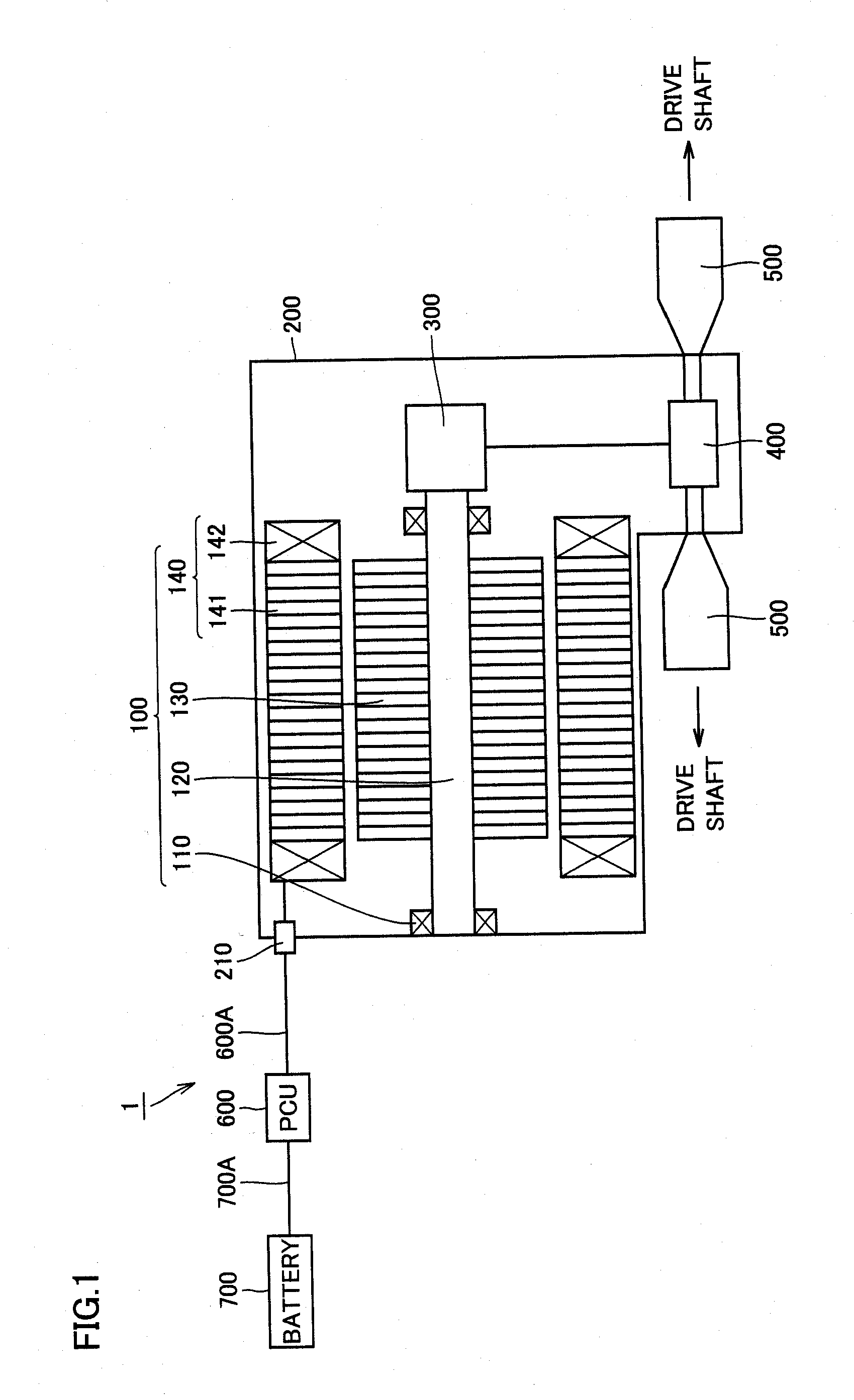
[0038]FIG. 1 is a diagram schematically showing a structure of a drive unit to which a rotor according to an embodiment of the present invention is applied. In the example shown ...


PUM


Abstract

A rotor includes: a rotor core fixedly attached to a rotational shaft and having a magnet-inserted hole portion; a magnet inserted into the magnet-inserted hole portion; and a resin portion injected into the magnet-inserted hole portion. The rotor core is constructed by axially stacking a plurality of electromagnetic steel sheets. The electromagnetic steel sheets include: an electromagnetic steel sheet having the magnet-inserted hole portion and a weight-reducing-purpose hole portion provided separately from the magnet-inserted hole portion; and an electromagnetic steel sheet located on at least one axial end of the rotor core and having a portion covering the hole portion formed in the electromagnetic steel sheet.

Description

TECHNICAL FIELD[0001]The present invention relates to a rotor and a method of manufacturing the same as well as an electric vehicle, and particularly to a rotor included in a rotating electric machine and a method of manufacturing the rotor as well as an electric vehicle including the rotor.BACKGROUND ART[0002]Japanese Patent Laying-Open No. 2002-34187 (Patent Document 1) discloses a rotor in which a resin material fills a space between a hole provided in a rotor core and a permanent magnet embedded in the hole so as to secure the permanent magnet to the rotor core.[0003]Japanese Patent Laying-Open No. 2005-51826 (Patent Document 2) discloses a rotor of an electric rotating machine in which a plurality of permanent magnets are arranged in an outer peripheral portion of a rotor core and a pair of end plates are secured to the two axial ends of the rotor core.[0004]It is desired to improve the drive efficiency of the rotating electric machine. Therefore, regarding the rotor as well, i...

Claims


Application Information

Patent Timeline
IPC IPC(8): H02K21/14H02K15/03
CPCH02K1/276H02K1/2766Y10T29/49012Y02T10/641H02K15/03B60L7/14B60L2220/52B60L50/51B60L58/40H02K7/006Y02T10/64Y02T10/70Y02T90/40
Inventor HARUNO, KENTAROTAKEUCHI, TAKETOAMANO, KATSUMIFUKUMOTO, TAKASHIUEDA, KAZUTOSHI
Owner TOYOTA JIDOSHA KK
Why Eureka
Try Eureka