
Hazard and Threat Assessment System

a threat assessment and threat technology, applied in the field of fire alarm systems, can solve the problems of increasing the possibility of injury or death of the occupant, increasing the damage to the building, and increasing the injury of the occupants of the building

Inactive Publication Date: 2009-02-19
SIMPLEXGRINNELL
View PDF10 Cites 50 Cited by
  • Summary
  • Abstract
  • Description
  • Claims
  • Application Information

AI Technical Summary

Benefits of technology

"The patent describes a fire alarm system that can visually show the progression of a fire in a building using sensors that detect various aspects of the fire. The system analyzes the data from the sensors and determines the rate of change and duration of time the fire is occurring. This information is then displayed in a graphical way, which can help firefighters quickly assess the fire and make decisions on how to handle it. The system can also modify its operation based on the rate of change, such as turning on cameras or activating sprinklers. Overall, the system provides a better understanding of the fire and helps firefighters take quicker and more effective action."

Problems solved by technology

Any delay in exiting the building increases the possibility of injury or death for the occupants.
Any delay subjects the building to more damage and the building's occupants to more injury.

Method used


Image

  • Hazard and Threat Assessment System
  • Hazard and Threat Assessment System
  • Hazard and Threat Assessment System

Examples


Embodiment Construction

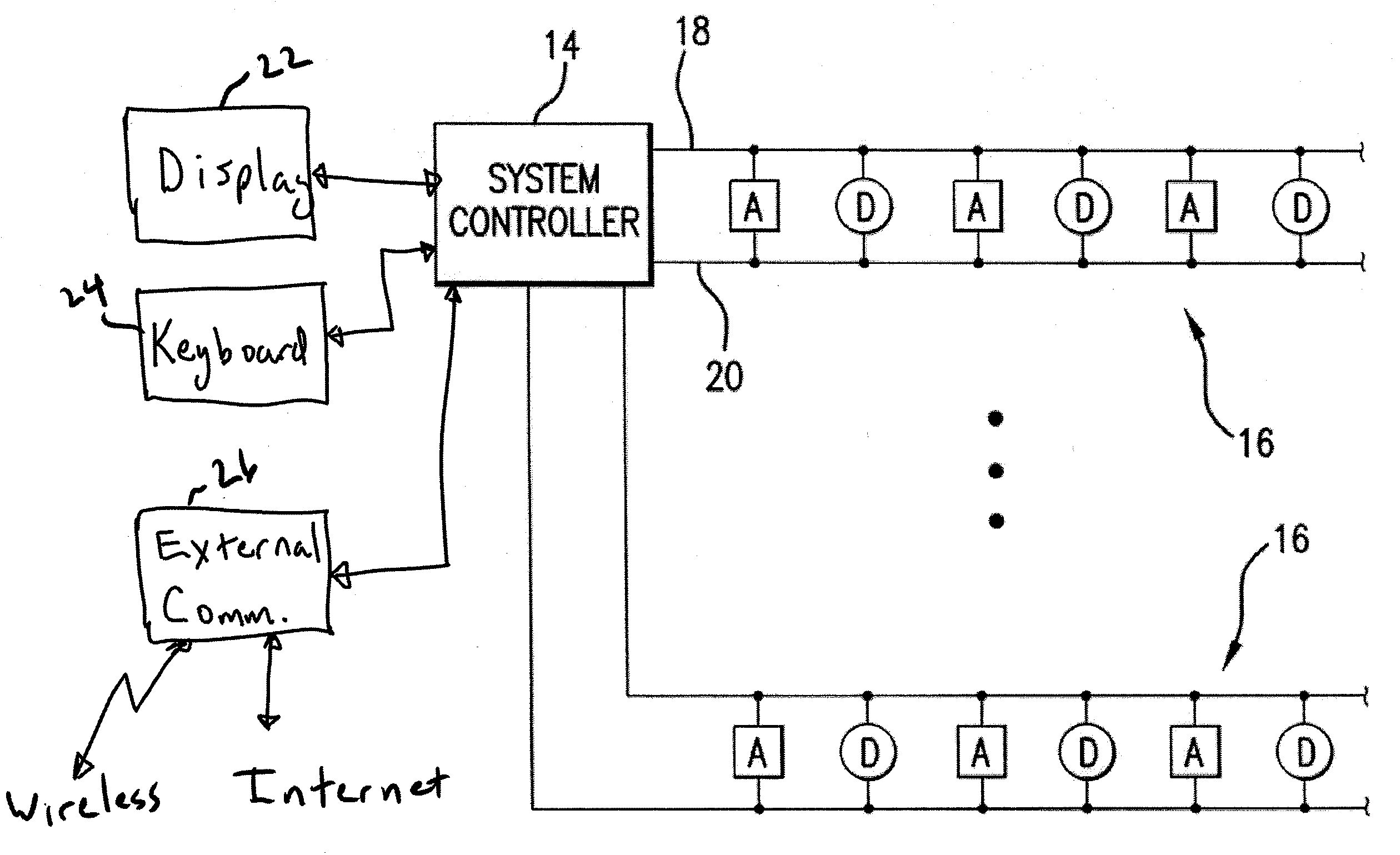
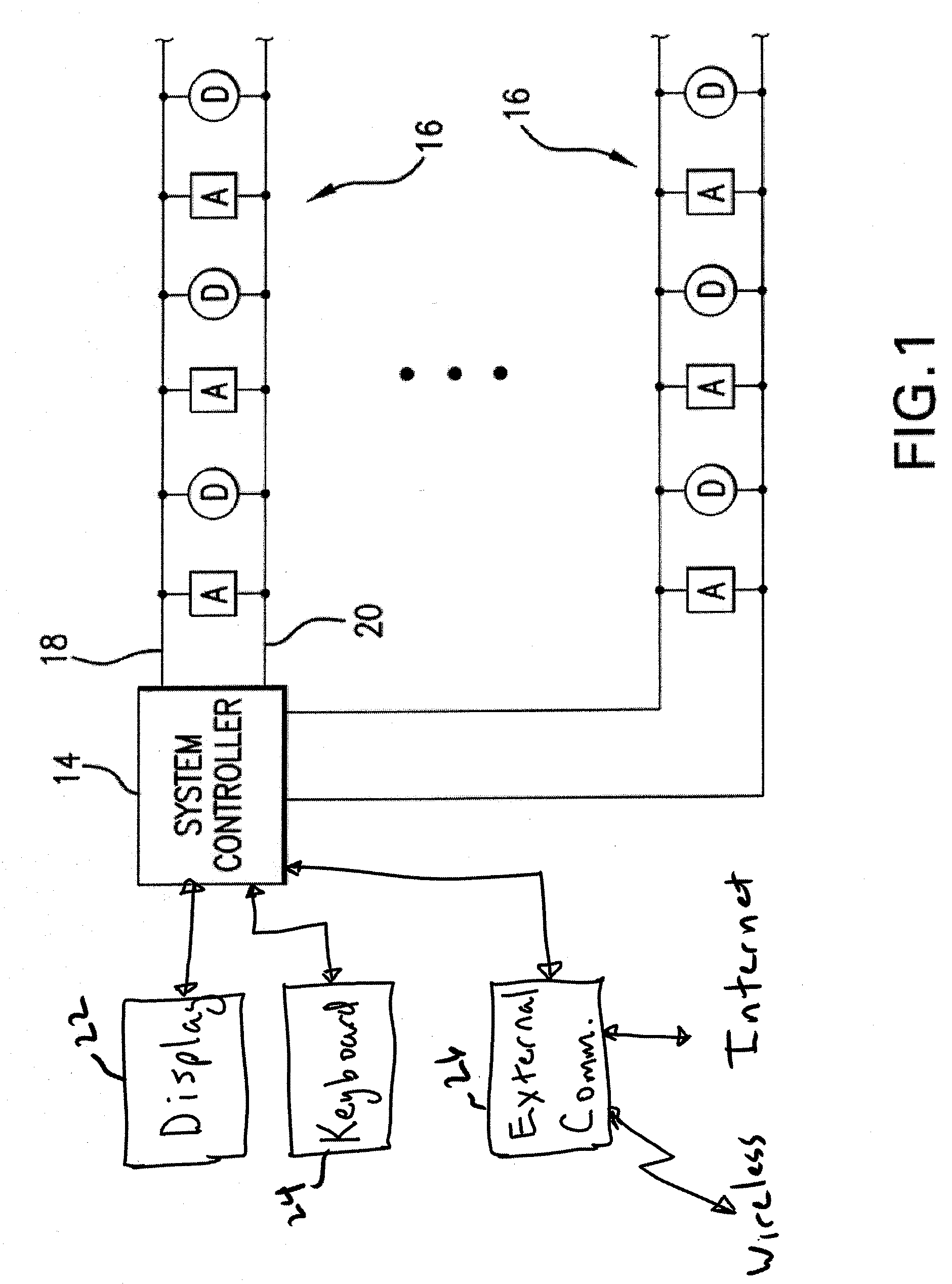
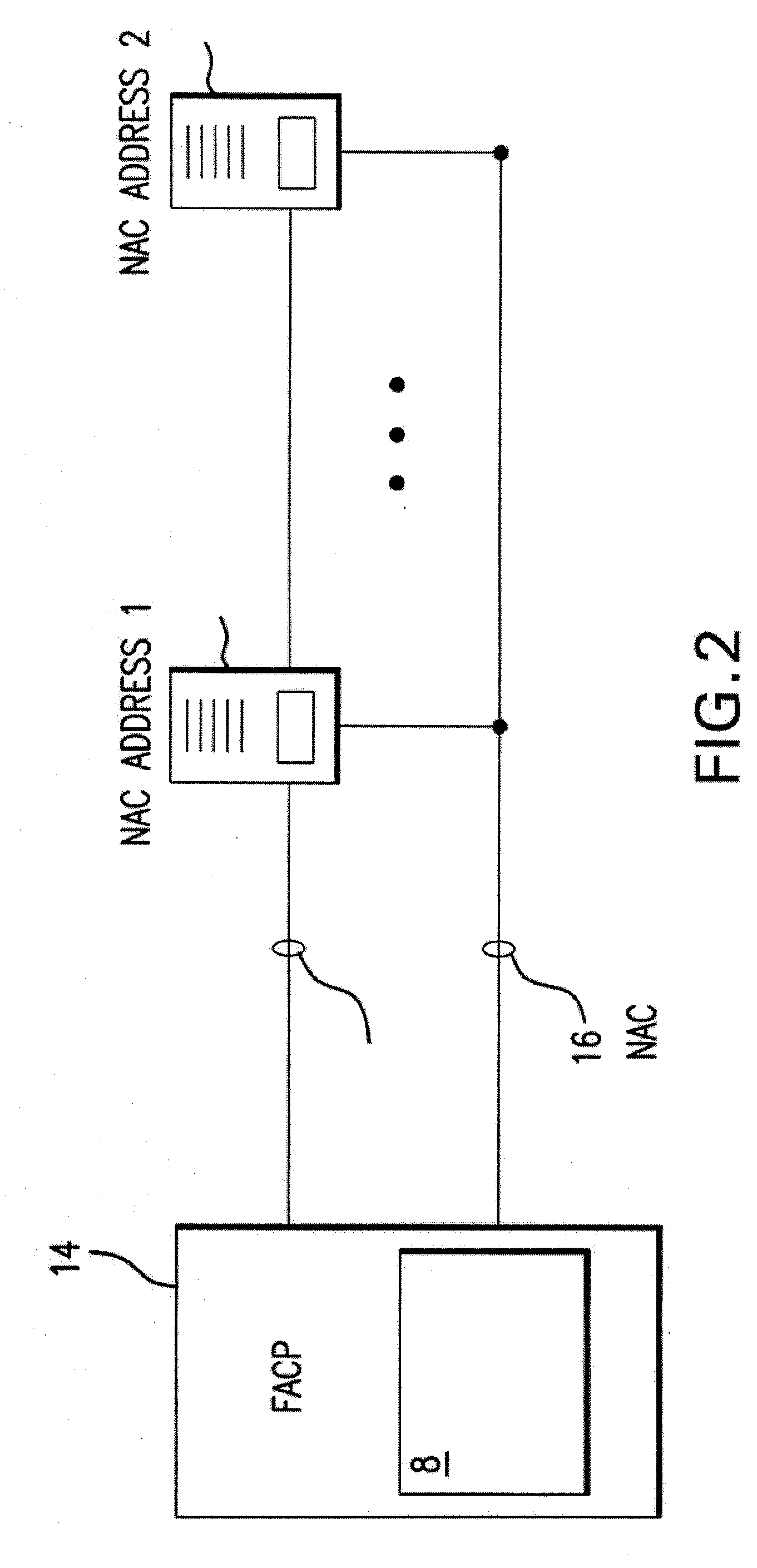
[0015]A system embodying the present invention is illustrated in FIG. 1. The system includes one or more notification appliance circuits (NACs), i.e., networks 16, having alarm condition detectors D and alarm notification appliances A. Alternatively, the detectors and notification appliances may be on separate networks. The detectors D may detect any aspect of a fire, such as smoke, temperature, or any combination thereof. The detectors D may be monitored by a system controller 14, as discussed in more detail below. The detectors D may periodically send a status signal indicating the status of the respective detector D. Further, the detectors D may detect the aspect related to the fire, and may determine whether to issue an alarm message to the system controller 14. For example, if smoke is detected (such as smoke detected above a predetermined amount), the detector D may send a signal to the system controller 14 indicating that smoke has been detected, indicating an alarm condition...


PUM


Abstract

A fire alarm system for graphically illustrating a fire alarm event is provided. The fire alarm system may receive fire alarm information from one or more fire sensors in a building, and may determine a rate of change of at least one aspect of the fire sensor. The rate of increase of temperature, the length that the fire sensor has been activated, the progression of the fire, etc. The rate of change may be graphically illustrated to enable the operator to quickly assess the fire alarm event. A fire alarm system, whose actions are modified by the rate of change of the fire alarm event, is also provided. Depending on the rate of change, one or more input devices (e.g., cameras or other sensors) one or more output devices (e.g., sprinklers, notification appliances, etc.) in the fire alarm system may be controlled.

Description

BACKGROUND OF THE INVENTION[0001]1. Technical Field[0002]The present invention relates to a fire alarm system, and more particularly to a fire alarm system that may graphically portray a fire alarm event and that may provide recommendations to respond to or combat the fire alarm event.[0003]2. Related Art[0004]Fire alarm systems typically include one or more detectors in one or more areas of a building, monitoring the areas of the building for fire. If a fire or smoke occurs, the detectors send a signal to a central controller indicating that a fire or smoke is occurring. The central controller may then send a notification signal to various notification appliances in the building. These may include visual and / or audio notification. The central controller may also indicate the status of the fire alarm system to an operator or first responder to assist in evacuating the building. For example, the central controller may indicate to the operator or first responder (fireman, building gua...

Claims


Application Information

Patent Timeline
Patent Type & Authority Applications(United States)
IPC IPC(8): A62C37/10
CPCG08B17/10G08B17/00G08B25/14
Inventor ZIMMERMAN, LARRY
Owner SIMPLEXGRINNELL
Learn More