Coupling device

a technology of coupling device and port, which is applied in the direction of slot antenna, polarised antenna unit combination, antenna, etc., can solve the problems of poor isolation and generate noise, and achieve the effect of improving port isolation

Active Publication Date: 2009-02-19
NAT TAIWAN UNIV
View PDF3 Cites 8 Cited by
  • Summary
  • Abstract
  • Description
  • Claims
  • Application Information

AI Technical Summary

Benefits of technology

[0008]The coupling device of the invention provides improved port isolation and polarization isolation.

Problems solved by technology

When a conventional coupling antenna 1 is utilized for transmitting wireless signal, noise is generated due to poor isolation between the first feed conductor 30 and the second feed conductor 40.

Method used


Image

  • Coupling device
  • Coupling device
  • Coupling device

Examples


Embodiment Construction

[0020]The following description is of the best-contemplated mode of carrying out the invention. This description is made for the purpose of illustrating the general principles of the invention and should not be taken in a limiting sense. The scope of the invention is best determined by reference to the appended claims.

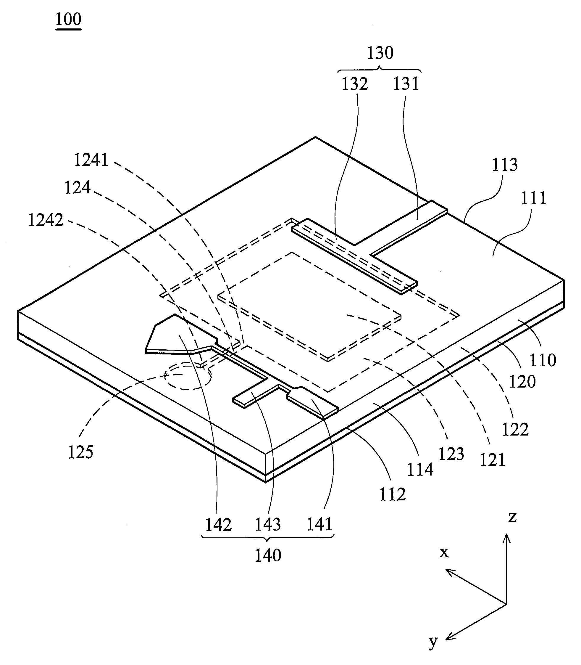
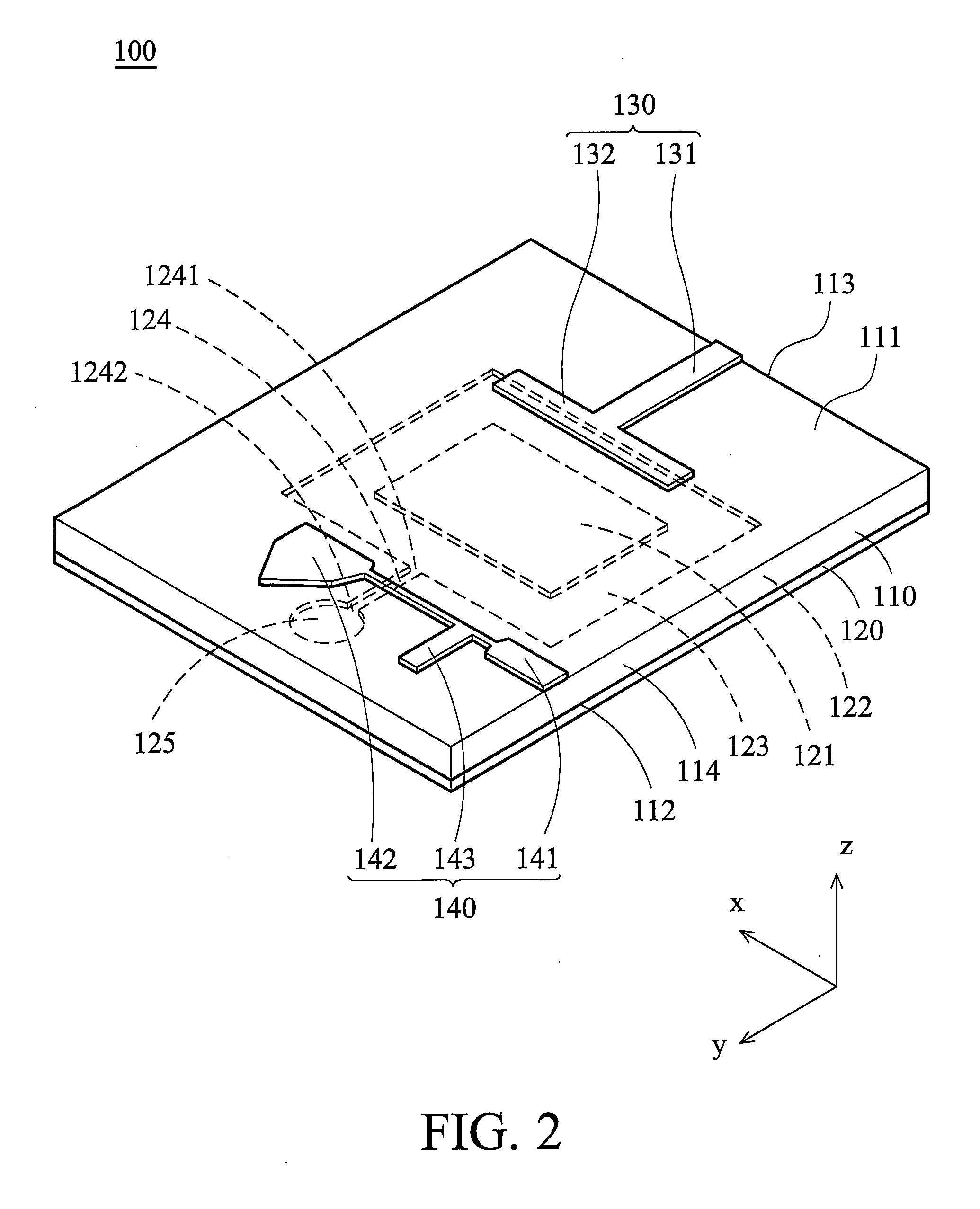
[0021]FIG. 2 shows a coupling device 100 of the invention which comprises a substrate 110, a ground element 120, a first feed conductor 130 and a second feed conductor 140. The substrate 110 comprises a first surface 111 and a second surface 112. The ground element 120 is disposed on the second surface 112. The first feed conductor 130 and the second feed conductor 140 are disposed on the first surface 111 corresponding to the ground element 120.

[0022]The ground element 120 comprises a first portion 121, a second portion 122, an annular groove 123, a feed slot 124 and a short slot 125. The annular groove 123 is located between the first portion 121 and the second porti...


PUM


Abstract

A coupling device is provided, including a substrate, a ground element, a first feed conductor and a second feed conductor. The substrate includes a first surface and a second surface. The ground element is disposed on the second surface, wherein the ground element includes a first portion, a second portion, an annular groove and a feed slot, the annular groove is located between the first portion and the second portion, enclosing the first portion, and a first end of the feed slot is connected to the annular groove. The first feed conductor is disposed on the first surface corresponding to the annular groove, wherein the first feed conductor couples the ground element to feed a current signal. The second feed conductor is disposed on the first surface corresponding to the feed slot, wherein second feed conductor couples the feed slot to feed a magnetic fluid signal.

Description

BACKGROUND OF THE INVENTION[0001]1. Field of the Invention[0002]The invention relates to a coupling device, and more particularly to a coupling device with improved isolation.[0003]2. Description of the Related Art[0004]FIG. 1 shows a conventional coupling antenna 1 comprising a substrate 10, a ground element 20, a first feed conductor 30 and a second feed conductor 40. The substrate 10 comprises a first surface 11 and a second surface 12. The ground element 20 is disposed on the second surface 12, which comprises a first portion 21, a second portion 22 and an annular groove 23. The annular groove 23 is located between the first portion 21 and the second portion 22 enclosing the first portion 21. The first feed conductor 30 is disposed on the first surface 11 corresponding to the first portion 21 and the annular groove 23. The second feed conductor 40 is disposed on the first surface 11 corresponding to the first portion 21 and the annular groove 23.[0005]When a conventional couplin...

Claims


Application Information

Patent Timeline
Patent Type & Authority Applications(United States)
IPC IPC(8): H01Q15/24
CPCH01Q21/24H01Q13/106
Inventor LIN, YI-CHENGHUNG, KUO-FONG
Owner NAT TAIWAN UNIV
Why Eureka
Try Eureka