Supercharge Your Innovation With Domain-Expert AI Agents!

Magnetic induction flowmeter having a plastic measuring tube

a technology of induction flowmeter and measuring tube, which is applied in the direction of electromagnetic flowmeter, volume/mass flow, measurement devices, etc., can solve the problems of substantial material and fabrication expenditure, wear, cracking or even fracture of the measuring tube, etc., and achieve the effect of preventing destructive mechanical loading

Inactive Publication Date: 2009-03-05
ABB (SCHWEIZ) AG
View PDF15 Cites 2 Cited by
  • Summary
  • Abstract
  • Description
  • Claims
  • Application Information

AI Technical Summary

Benefits of technology

[0009]A plastic measuring tube of a magnetic induction flowmeter is disclosed to the effect that, by using simple means, destructive mechanical loadings can be kept away from the measuring tube.
[0011]By using the force deflection means, which are additional to this extent, destructive mechanical loadings can be managed in a simple way. In this case, in the design of the measuring tube itself, the loadings acting from the pipeline system can remain disregarded. This is because these loadings are substantially kept away from the measuring tube by the additional means for force deflection. The measuring tube itself merely has to withstand other loadings which, for example, are produced by pressure and temperature of the flow medium flowing through. As a result, the measuring tube itself can be quite thin-walled and therefore save material. Accordingly, a low inherent mass can be achieved.
[0013]According to a further exemplary embodiment, the end connection can be produced via an annular disk in each case which is arranged at the end of the measuring tube and which is fixed radially internally to the measuring tube and radially externally to the metal tube or the rod elements or the like. To this extent, the rod elements themselves can be rectilinear and can run parallel to the measuring tube axis. Thus, starting from one end of the measuring tube, the force flow runs via the annular disk arranged here, then via the metal tube or the rod elements or the like to the other annular disk and from there into the pipeline leading onward. The measuring tube itself is thus freed to the greatest extent from the disruptive mechanical loadings.
[0014]The annular disks to be used in conjunction with the metal tube or the rod elements within the context of the means for diverting the axial and thrust forces can be produced from a rigid plastic or from a metal. In the latter case, a particularly high mechanical loadbearing ability can be achieved with relative low material thicknesses. However, an annular disc produced from metal must be fixed to the outside of the measuring tube so as not to contact the substance to be measured. This is because, by means of this measure improving the exemplary embodiment further, it is possible to ensure that disruptive electric potentials are not passed on to the electrically conductive flow medium via the metallic annular disks.
[0015]The fixing of the annular disk to the outside of the measuring tube can be carried out cohesively by means of adhesive bonding or welding. If the annular disk is comprised of metal, this can be fixed to the plastic measuring tube in a straightforward manner by means of adhesive bonding. If a plastic annular disk is to be used, this can possibly be fixed by means of welding to the measuring tube, likewise can be comprised of the same plastic. Further alternative exemplary embodiments for cohesive fixings are also conceivable. As compared with other types of fixing, the exemplary types of fixing variously set forth above can be used because of the simple implementation in terms of fabrication.

Problems solved by technology

In addition, magnetic induction flowmeters have no parts which move or project into the measuring tube and which, in particular, are subject to wear.
Thus, depending on the installation situation, disruptive mechanical influences in the form of axial forces and / or thrust forces can occur on the measuring tube and, in the extreme case, can lead to cracking or even to fracture of the measuring tube.
Although these problems can be counteracted by an appropriate material selection and also by generous dimensioning of the wall thickness, this is often associated with considerable expenditure on material and fabrication.

Method used


Image

  • Magnetic induction flowmeter having a plastic measuring tube
  • Magnetic induction flowmeter having a plastic measuring tube
  • Magnetic induction flowmeter having a plastic measuring tube

Examples


Embodiment Construction

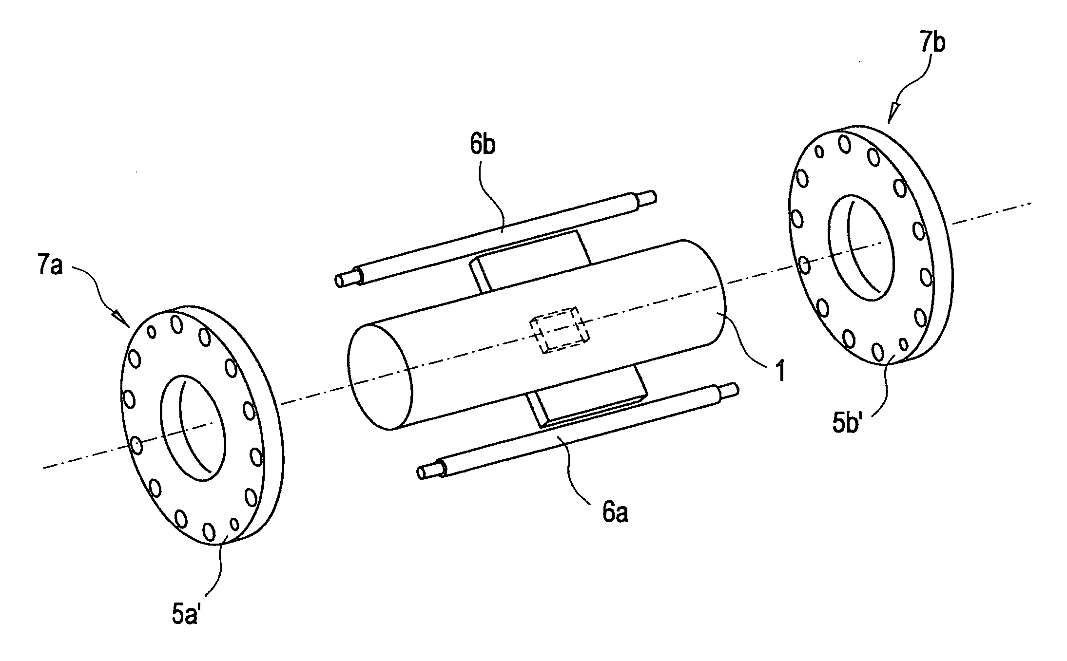
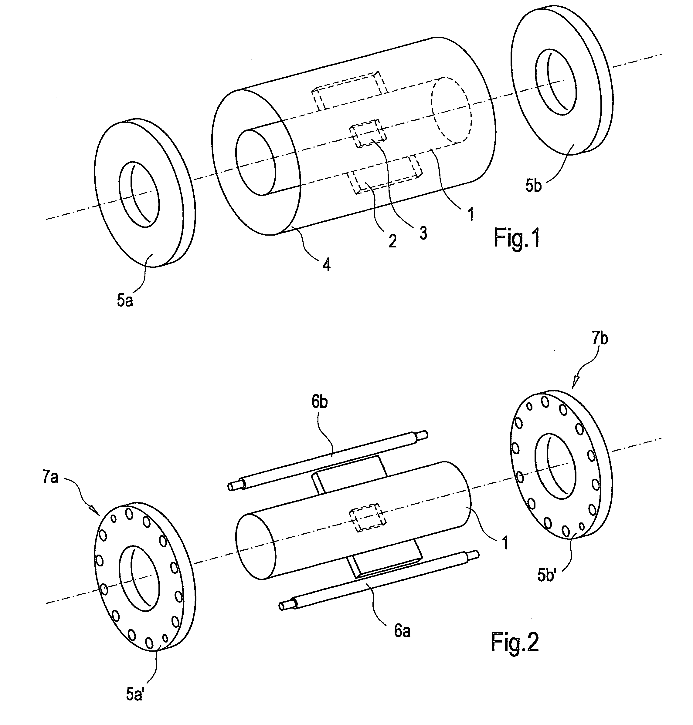
[0021]According to FIG. 1, the exemplary magnetic induction flowmeter illustrated schematically here has a plastic measuring tube 1. In this exemplary embodiment, the plastic used is polyether ketone (PEEA). Arranged on the outside of the measuring tube 1 is a magnetic unit 2, which generates a magnetic field aligned substantially at right angles to the flow direction of the conductive flow medium to be measured. The voltage induced in the flow medium in this way is registered via two measuring electrodes 3 introduced opposite each other into the wall of the measuring tube 1 and is then passed on to a signal processing device, not further illustrated.

[0022]The quite thin-walled measuring tube 1, comprising plastic, is also equipped with means for diverting external mechanical loadings, which primarily act via the pipeline system. In this exemplary embodiment, these means for diverting the axial and thrust forces causing loadings comprise a metal tube 4 surrounding the measuring tube...


PUM


Abstract

A magnetic induction flowmeter has a plastic measuring tube (1), which can be inserted into a pipeline system, having at least two mutually opposite measuring electrodes (3) introduced into the wall of the measuring tube (1) in order to register a measuring voltage, a magnetic unit (2), likewise arranged on the outside of the measuring tube (1), generating a magnetic field aligned substantially at right angles to the flow direction of the conductive flow medium to be measured. The plastic measuring tube (1) is equipped with means for diverting axial and thrust forces which act from the outside on the measuring tube (1) inserted into the pipeline system, in order to keep destructive mechanical loadings away from the measuring tube (1).

Description

CROSS REFERENCE TO RELATED APPLICATIONS[0001]This application claims priority under 35 U.S.C. §119 to German Application 10 2006 008 433.0 filed in Germany on 23 Feb. 2006, the entire contents of which are hereby incorporated by reference in their entireties.FIELD[0002]A magnetic induction flowmeter having a plastic measuring tube is disclosed, which can be inserted into a pipeline system, having at least two mutually opposite measuring electrodes introduced into the wall of the measuring tube in an electrically insulated manner in order to register a measuring voltage, and a magnetic unit, likewise arranged on the outside of the measuring tube, generating a magnetic field aligned substantially at right angles to the flow direction of the conductive flow medium to be measured.BACKGROUND INFORMATION[0003]A magnetic induction flow meter is used as a flow meter for liquids, pulps and pastes which have a specific minimum electric conductivity. This type of flowmeter is distinguished by ...

Claims


Application Information

Patent Timeline
Patent Type & Authority Applications(United States)
IPC IPC(8): G01F1/58
CPCG01F1/588G01F1/58
Inventor KEESE, DIETER
Owner ABB (SCHWEIZ) AG
Features
  • R&D
  • Intellectual Property
  • Life Sciences
  • Materials
  • Tech Scout
  • Unparalleled Data Quality
  • Higher Quality Content
  • 60% Fewer Hallucinations
Learn More