Bottom Plate Regulation of Charge Pumps

Active Publication Date: 2009-03-05
SANDISK TECH LLC
View PDF99 Cites 78 Cited by
  • Summary
  • Abstract
  • Description
  • Claims
  • Application Information

AI Technical Summary

Problems solved by technology

Typical charge pump designs, such as conventional Dickson-type pumps, are suited for supplying capacitive loa

Method used


Image

  • Bottom Plate Regulation of Charge Pumps
  • Bottom Plate Regulation of Charge Pumps
  • Bottom Plate Regulation of Charge Pumps

Examples


Embodiment Construction

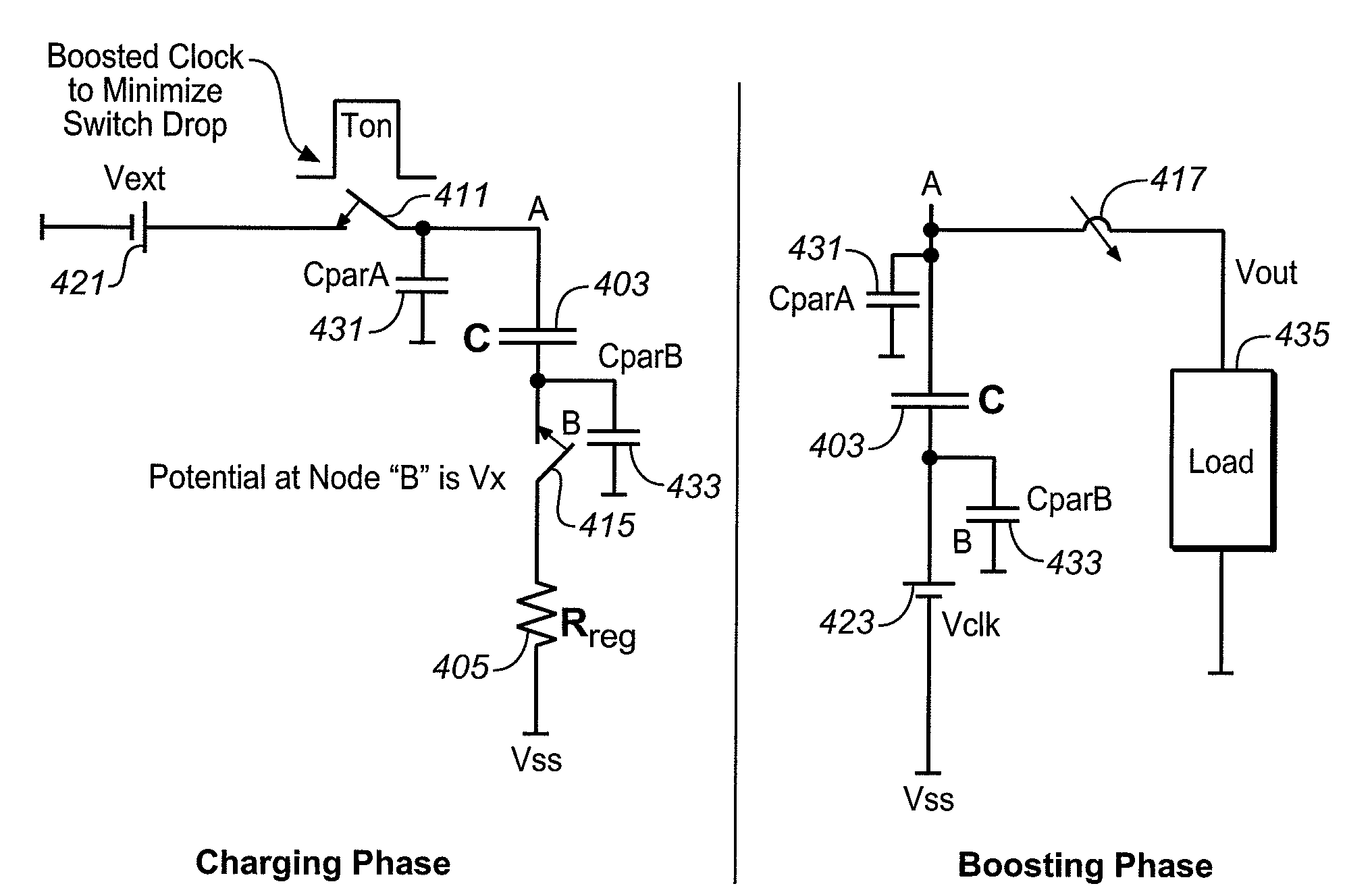
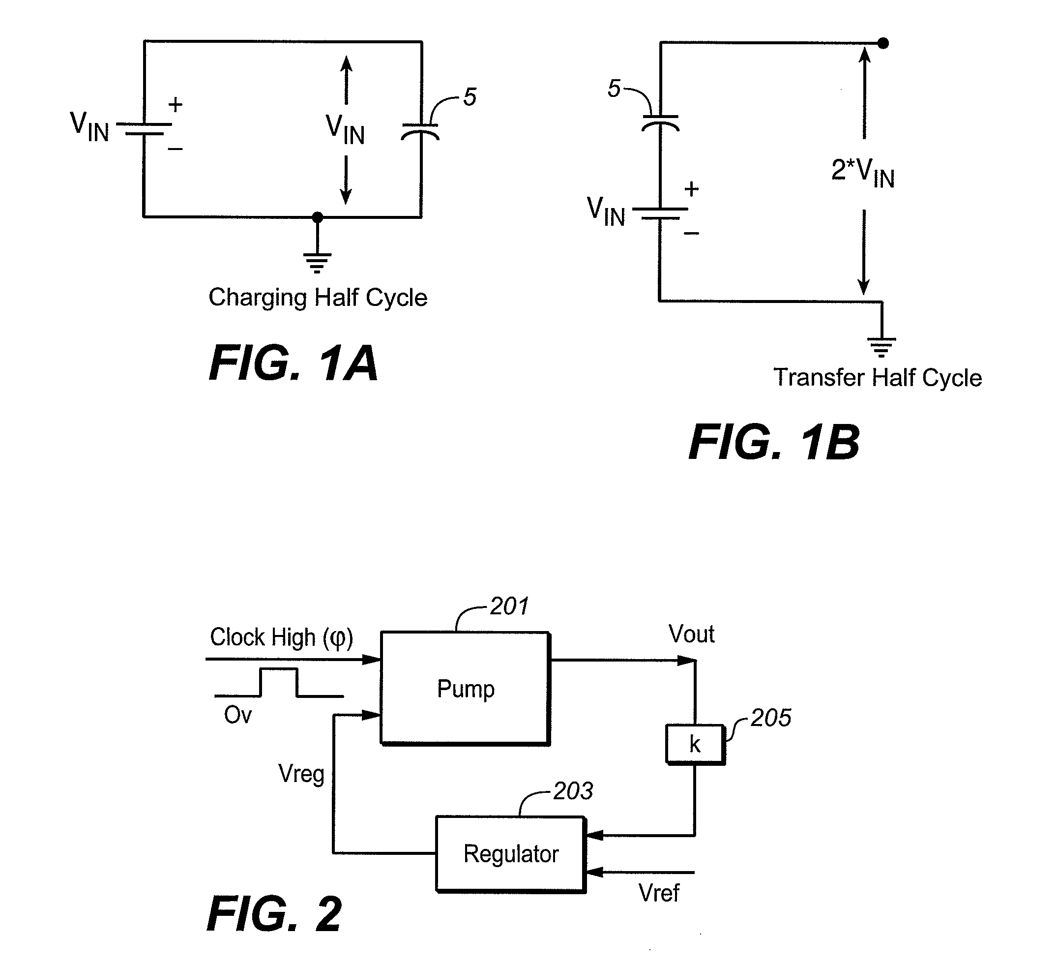
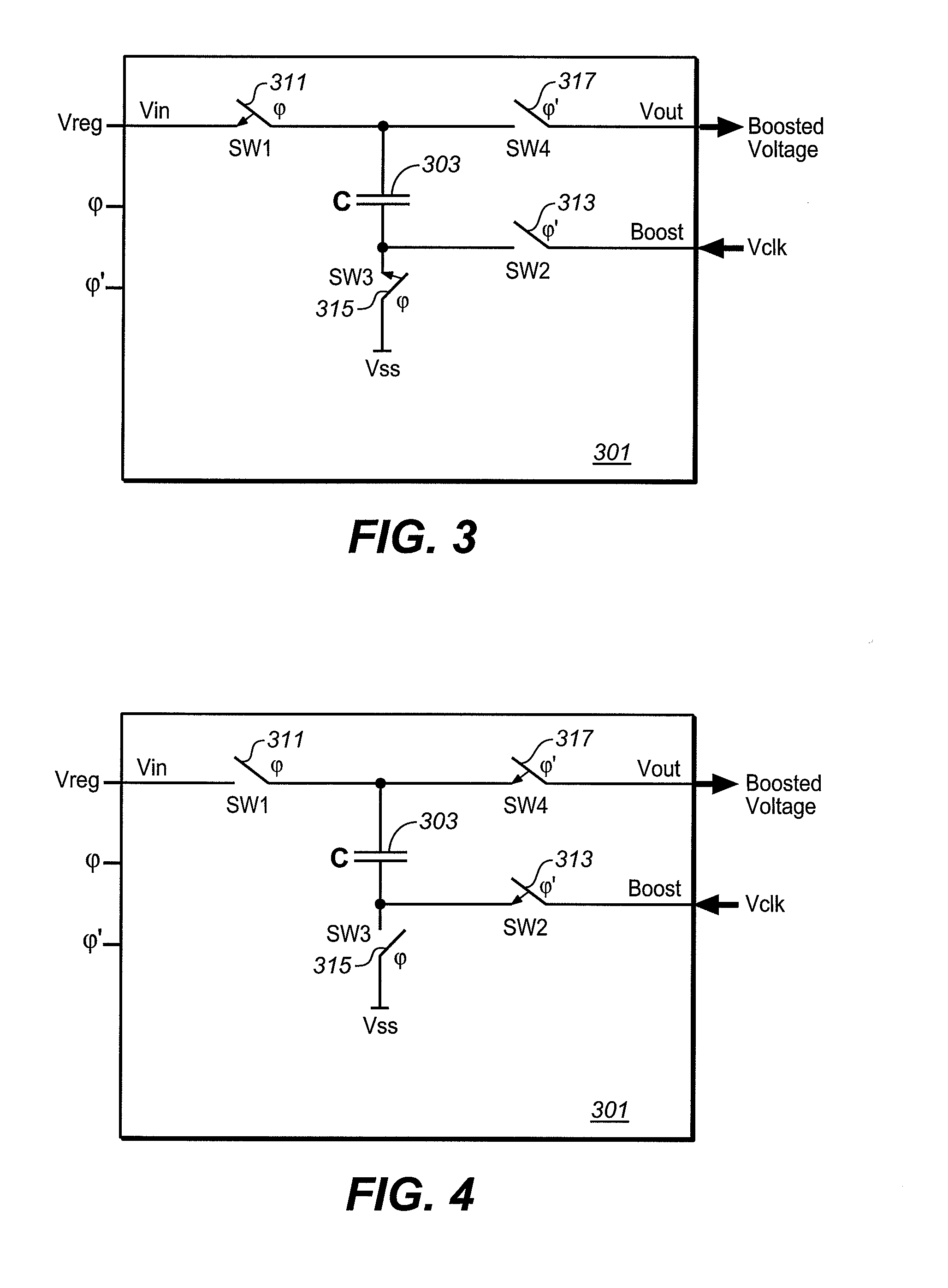
[0014]As noted in the Background section, many conventional charge pumps, such as those of the Dickerson type, are suited for supplying capacitive loads, but the efficiency of such pumps drops when they are required to supply a DC current load. Charge pumps are often in as peripheral devices in applications having such requirements, as in flash memories. The arrangement presented here uses a scheme that can achieve much higher efficiency when supplying DC loads than prior art techniques, such as the normal Vt Cancellation techniques are used to improve the efficiency. In particular, the following discussion describes a pump scheme that focuses on a bottom plate regulation scheme that provides higher efficiency and less ripple when compared to existing schemes.

[0015]The improvements described can be incorporated into various charge pump designs, both of the Dickson type mentioned in the Background section as well as more general designs.

[0016]More information on Dickenson type pumps,...


PUM


Abstract

Techniques of operating a charge pump are described. The charge pump is connectable to receive a clock signal and a regulating voltage and provide an output voltage. The charge pump can have one or multiple stages, each of the stages will include a capacitor. During the charging phase, the regulating voltage is used to regulate the potential of the capacitor's bottom plate. During the boosting phase, the capacitor's top plate is connected to supply the output for the stage and the bottom plate is connected to receive the stage's input. Each stage will also have a set of switching elements, allowing the capacitor to be alternately connected in the charging and boosting phases. For the first stage, the input is derived from the clock signal, and for any subsequent stages, the input will be the output of the preceding stage. The last stage provides the output voltage of the pump.

Description

CROSS-REFERENCE TO RELATED APPLICATIONS[0001]This application is related to U.S. application Ser. No. ______, of Prajit Nandi and Sridhar Yadala, entitled “Bottom Plate Regulated Charge Pump,” which is filed concurrently with the present application.FIELD OF THE INVENTION[0002]This invention pertains generally to the field of charge pumps and more particularly to a charge pump using a bottom plate regulation scheme.BACKGROUND[0003]Charge pumps use a switching process to provide a DC output voltage larger than its DC input voltage. In general, a charge pump will have a capacitor coupled to switches between an input and an output. During one clock half cycle, the charging half cycle, the capacitor couples in parallel to the input so as to charge up to the input voltage. During a second clock cycle, the transfer half cycle, the charged capacitor couples in series with the input voltage so as to provide an output voltage twice the level of the input voltage. This process is illustrated ...

Claims


Application Information

Patent Timeline
IPC IPC(8): G05F1/10
CPCH02M3/07
Inventor NANDI, PRAJITYADALA, SRIDHAR
Owner SANDISK TECH LLC
Why Eureka
Try Eureka