Optical Linear and Rotation Displacement Sensor

a technology of optical displacement sensor and rotation displacement sensor, which is applied in the field of noncontact optical displacement sensor, can solve the problems of unintentional unevenness or roughness of the surface of microscopic asperities

Inactive Publication Date: 2009-03-05
LORD CORP
View PDF26 Cites 14 Cited by
  • Summary
  • Abstract
  • Description
  • Claims
  • Application Information

AI Technical Summary

Problems solved by technology

Microscopic asperities are unintentionally occurring unevenness or roughness of a surface.

Method used


Image

  • Optical Linear and Rotation Displacement Sensor
  • Optical Linear and Rotation Displacement Sensor
  • Optical Linear and Rotation Displacement Sensor

Examples


Embodiment Construction

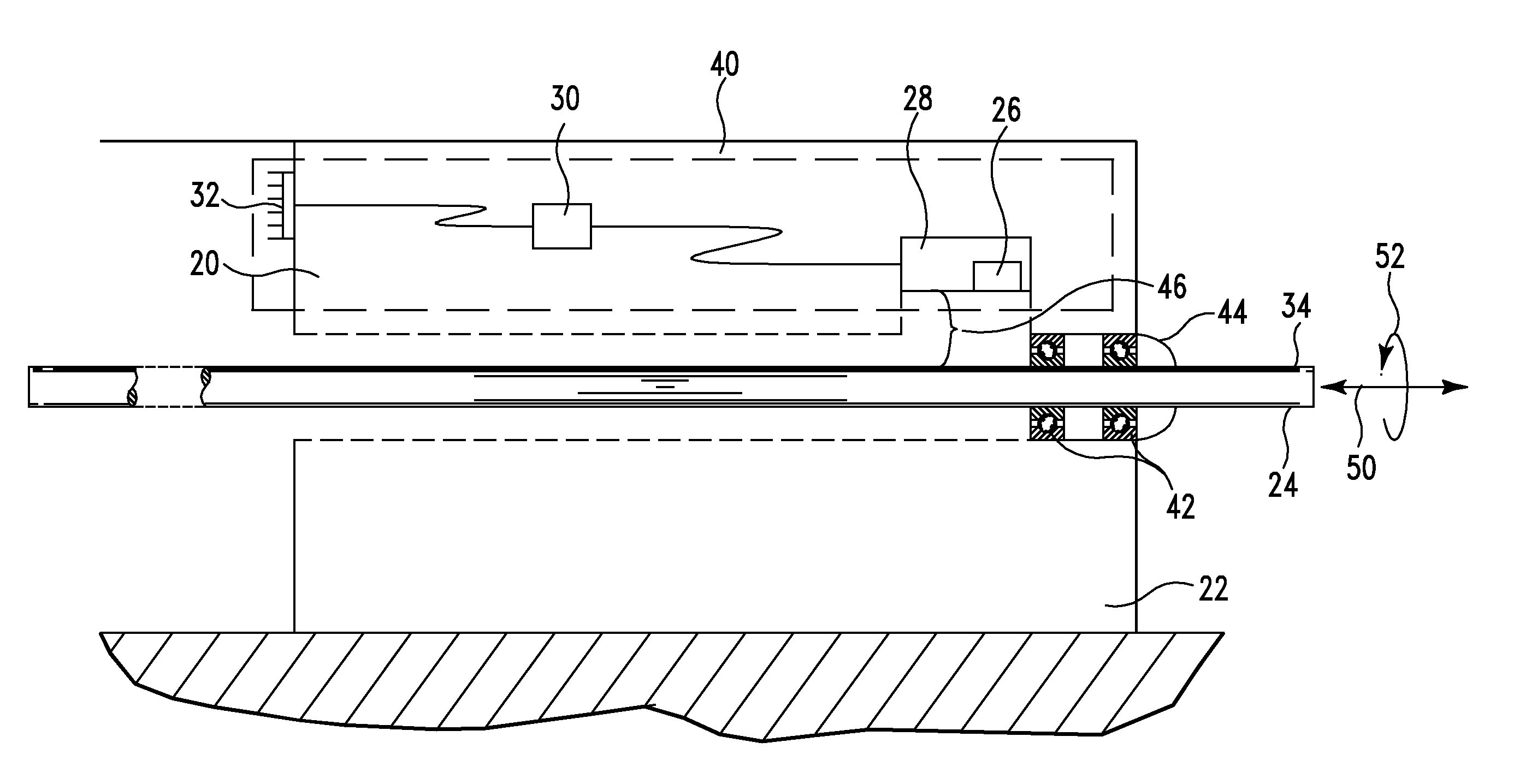
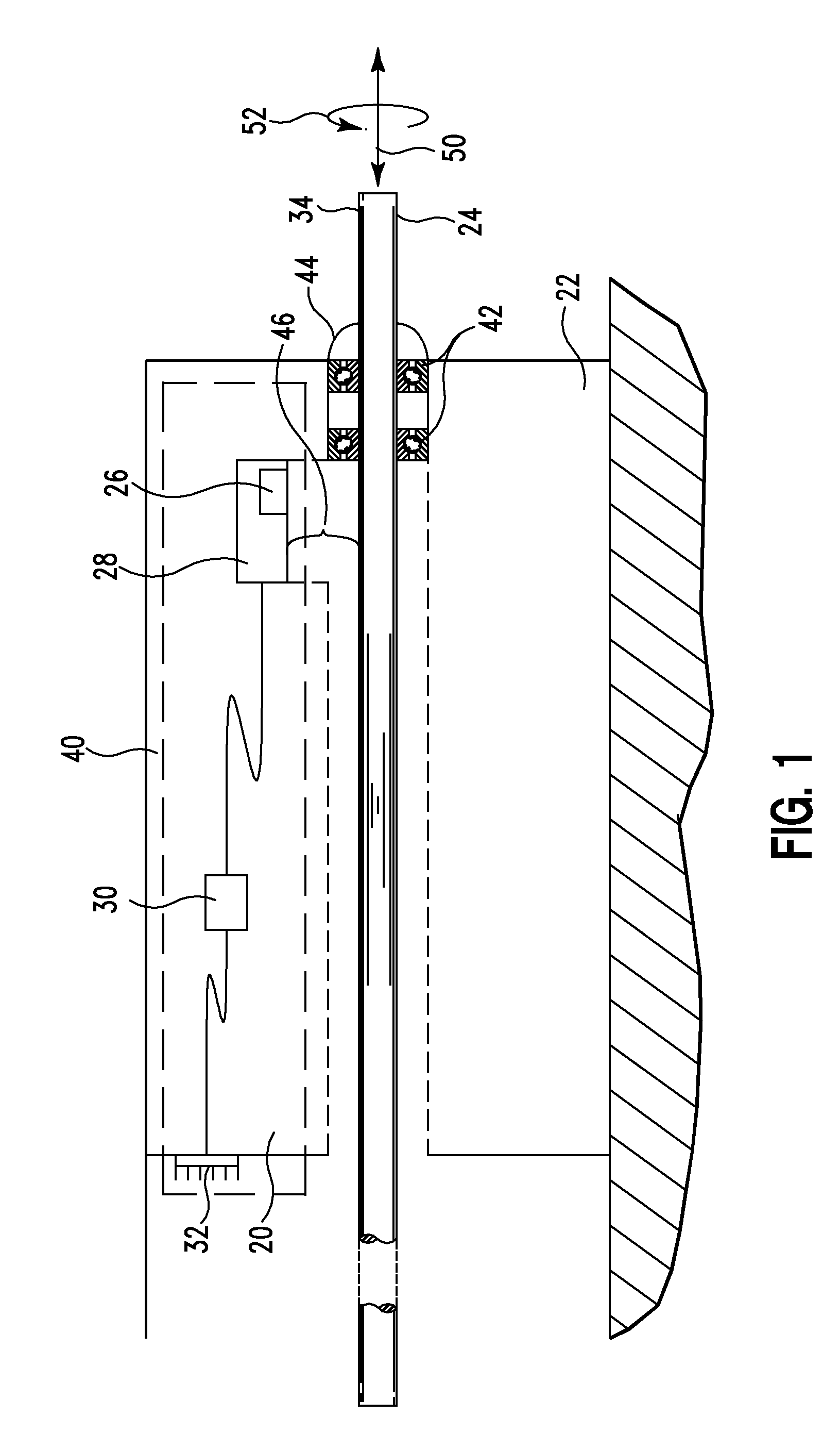
[0030]The present applicants recognized advantage if a non-planar target object did not need to be engineered in any way. This would allow for the ability to measure displacement and rotation of target objects that are not designed specifically for displacement sensing. For example, the present applicants considered the case where the depth of insertion of a disposable acupuncture needle into a patient is to be measured. As described herein below they found a way to implement a non-contacting sensor that uses the surface of a standard acupuncture needle as its target.

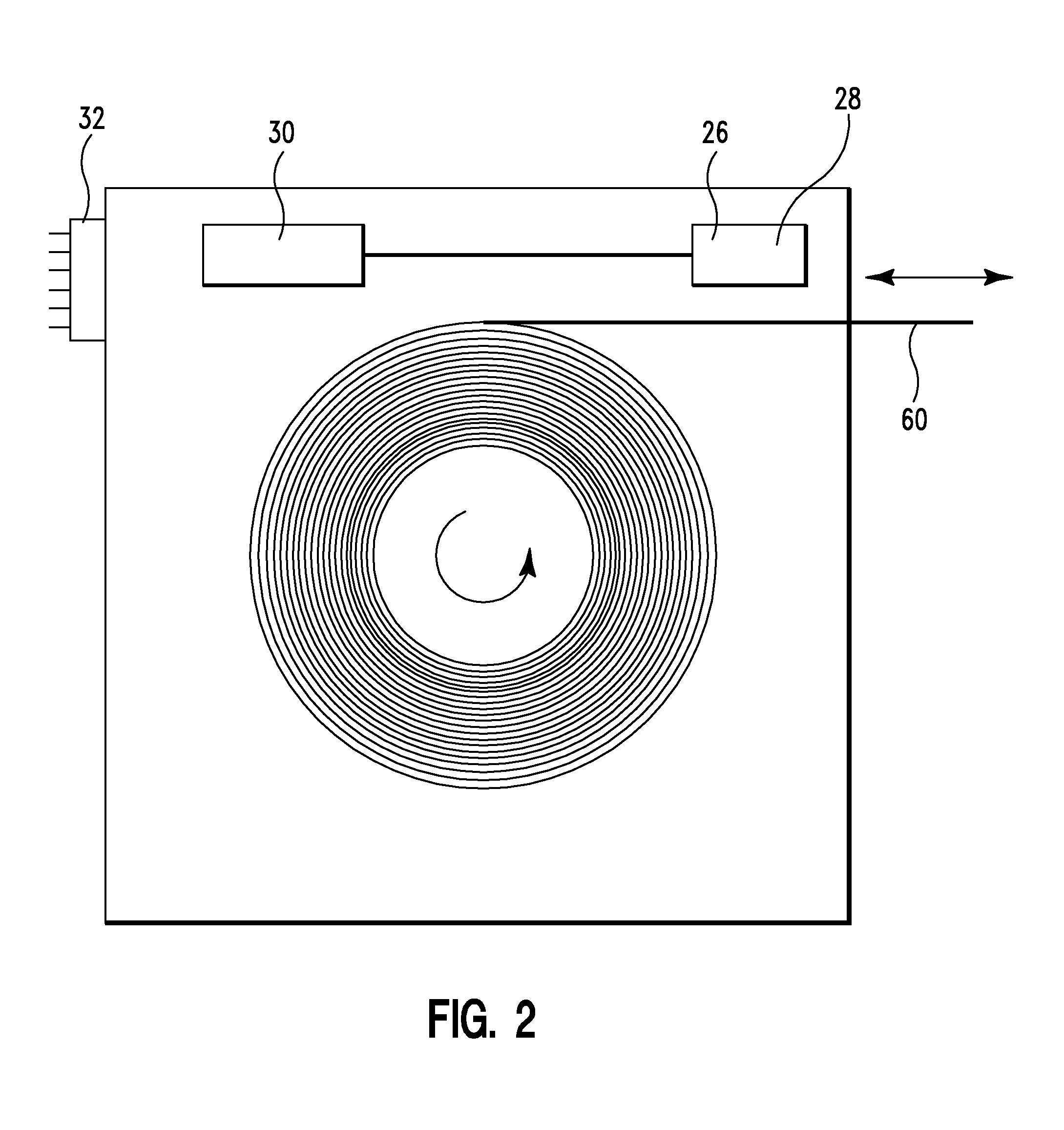
[0031]The present applicants recognized that computer mouse sensors can be used to accurately detect the translation and rotation of non-planar targets, such as elongate members, including wires, threads, filaments, needles, tubes, catheters, rods and tapes. They found that no special preparation of the surface of the wire or needle was required. They found that this optical sensing technology was ideal for measuring th...


PUM


Abstract

A system includes a measuring tool, a fixture, and a rotatable target. The measuring tool includes a light source, an imaging device, and an electronic circuit. The fixture allows the rotatable target to rotate about an axis. The rotatable target includes a surface having microscopic asperities. The imaging device is mounted to provide a sequence of images derived from said microscopic asperities. The electronic circuit is connected to the imaging device for measuring rotation of the rotatable target from the sequence of images.

Description

RELATED PATENT APPLICATIONS AND PRIORITY[0001]This application claims priority of Provisional Patent Application 60 / 968,992, filed Aug. 30, 2007, incorporated herein by reference.FIELD[0002]This patent application generally relates to optical displacement sensors. More particularly it relates to non-contact optical displacement sensors.BACKGROUND[0003]Many electrical and mechanical applications involve measuring relative motion between two objects. This motion may include translation, rotation, or a combination of both. A wide variety of sensing technologies have been developed to accomplish this task.[0004]An important category of such displacement sensors are those that accomplish their measurement in a non-contacting manner. In this category no direct mechanical connection exists between the two objects or between the measuring device, which may be mounted to move with one of the objects, and the other object. The advantages of non-contacting measurement include: zero friction, h...

Claims


Application Information

Patent Timeline
Patent Type & Authority Applications(United States)
IPC IPC(8): G01B11/14G01B7/14
CPCA61B2017/3405A61B2019/462A61H39/086A61H2201/5064G01B11/26G01B7/02G01B11/002G01B11/02A61H2201/5069A61B2090/062
Inventor CHURCHILL, DAVID L.ARMS, STEVEN W.
Owner LORD CORP
Why Eureka
Try Eureka