Microelectromechanical sensor with improved mechanical decoupling of sensing and driving modes

a microelectromechanical sensor and driving mode technology, applied in the direction of acceleration measurement using interia force, speed measurement using gyroscopic effects, electric/magnetic means, etc., can solve the problem of improper ratio between stiffness in orthogonal direction z, impaired and lack of perfect decoupling between driving and sensing movements

Active Publication Date: 2009-03-12
STMICROELECTRONICS SRL
View PDF14 Cites 142 Cited by
  • Summary
  • Abstract
  • Description
  • Claims
  • Application Information

AI Technical Summary

Problems solved by technology

The presence of the central anchorage also enables rejection of spurious linear accelerations along the axes x and y, given that the arrangement of elastic anchorage elements 8 is extremely rigid in these directions, and does not enable displacement of the sensing masses.
In detail, the Applicant has realized that flaws in the manufacturing process or improper choices in the structure geometry (e.g. a thickness too small with respect to the dimensions in the plane of the sensor xy, or an improper shape of the elastic elements) may result in the microelectromechanical structur

Method used


Image

  • Microelectromechanical sensor with improved mechanical decoupling of sensing and driving modes
  • Microelectromechanical sensor with improved mechanical decoupling of sensing and driving modes
  • Microelectromechanical sensor with improved mechanical decoupling of sensing and driving modes

Examples


Embodiment Construction

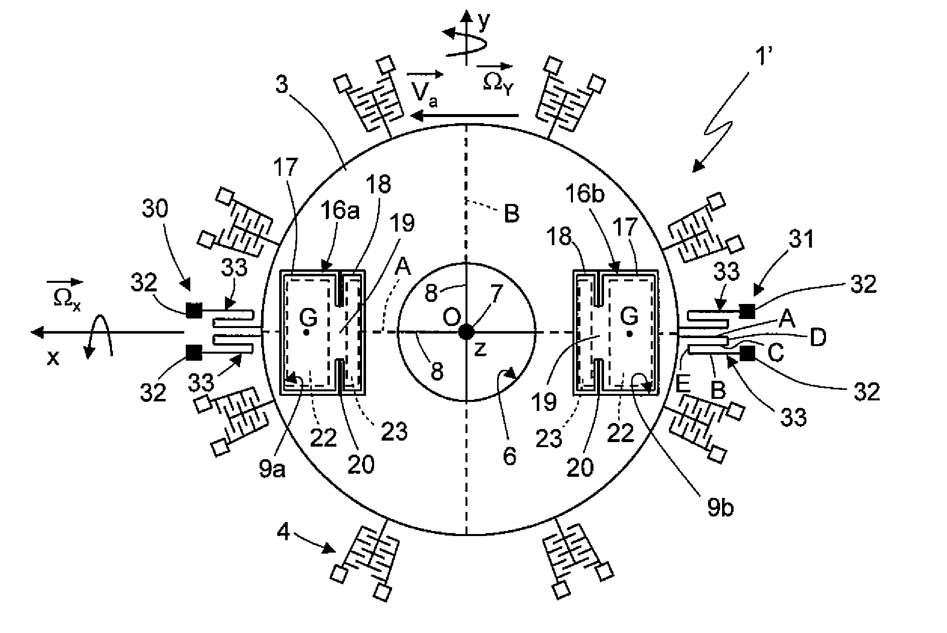
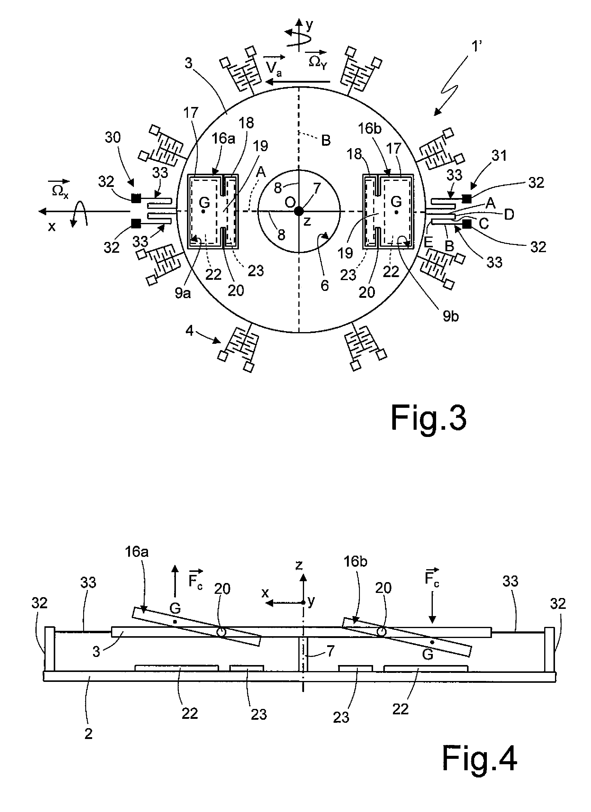
[0033]One embodiment of the present invention envisages the provision of additional anchorages and elastic anchorage elements connected to the driving mass 3 in order to improve the stiffness of the same driving mass 3 for movements outside the plane of the sensor xy.

[0034]As shown in FIG. 3 wherein same reference numerals refer to same elements as those in FIG. 1, the microelectromechanical sensor, here denoted with 1′, differs from the sensor described with reference to FIG. 1 in that it further comprises a first and a second external anchorage arrangements 30, 31, coupled to the driving mass 3.

[0035]In detail, the first and second external anchorage arrangements 30, 31 are positioned externally of the driving mass 3, and are coupled to opposite sides of the same driving mass 3, with respect to the empty space 6 and center O; in the exemplary embodiment shown in FIG. 3, the first and second external anchorage arrangements 30, 31 are also aligned along the first axis x, and are dia...


PUM


Abstract

A driving mass of an integrated microelectromechanical structure is moved with a rotary motion about an axis of rotation, and a sensing mass is connected to the driving mass via elastic supporting elements so as to perform a detection movement in the presence of an external stress. The driving mass is anchored to a first anchorage arranged along the axis of rotation by first elastic anchorage elements. The driving mass is also coupled to a pair of further anchorages positioned externally thereof and coupled to opposite sides with respect to the first anchorage by further elastic anchorage elements; the elastic supporting elements and the first and further elastic anchorage elements render the driving mass fixed to the first sensing mass in the rotary motion, and substantially decoupled from the sensing mass in the detection movement, the detection movement being a rotation about an axis lying in a plane.

Description

BACKGROUND[0001]1. Technical Field[0002]The present invention relates to a microelectromechanical sensor having improved mechanical decoupling of sensing and driving modes. In particular, in the following description reference will be made to a gyroscope (whether uniaxial, biaxial or triaxial), which can possibly operate as an accelerometer (whether uniaxial, biaxial or triaxial).[0003]2. Description of the Related Art[0004]As is known, microprocessing techniques enable formation of microelectromechanical structures or systems (the so-called MEMS) within layers of semiconductor material, which have been deposited (for example, in the case of a layer of polycrystalline silicon) or grown (for example, in the case of an epitaxial layer) on top of sacrificial layers, which are removed by chemical etching. Inertial sensors, accelerometers and gyroscopes obtained with this technology are encountering an increasing success, for example in the automotive field, in inertial navigation, or in...

Claims


Application Information

Patent Timeline
IPC IPC(8): G01P15/14
CPCG01C19/5712G01P15/18G01P15/14G01P15/125G01P2015/0828
Inventor CORONATO, LUCALUDOVICO, ALESSANDRO BALZELLIZERBINI, SARAH
Owner STMICROELECTRONICS SRL
Why Eureka
Try Eureka