
Particle motion sensor mounting for marine seismic sensor streamers

a motion sensor and streamer technology, applied in seismology, seismology, instruments, etc., can solve the problems of difficult interpretation of seismic signals, mechanical noise of streamer cables, and difficulty in inferring subsurface structures and compositions from seismic data

Inactive Publication Date: 2009-03-12
PGS AMERICA INC
View PDF39 Cites 46 Cited by
  • Summary
  • Abstract
  • Description
  • Claims
  • Application Information

AI Technical Summary

Benefits of technology

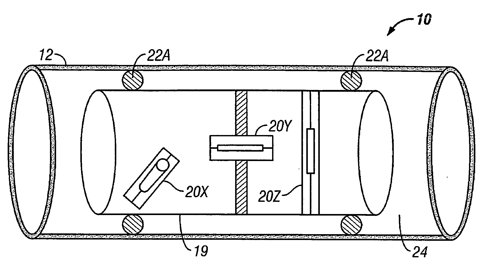
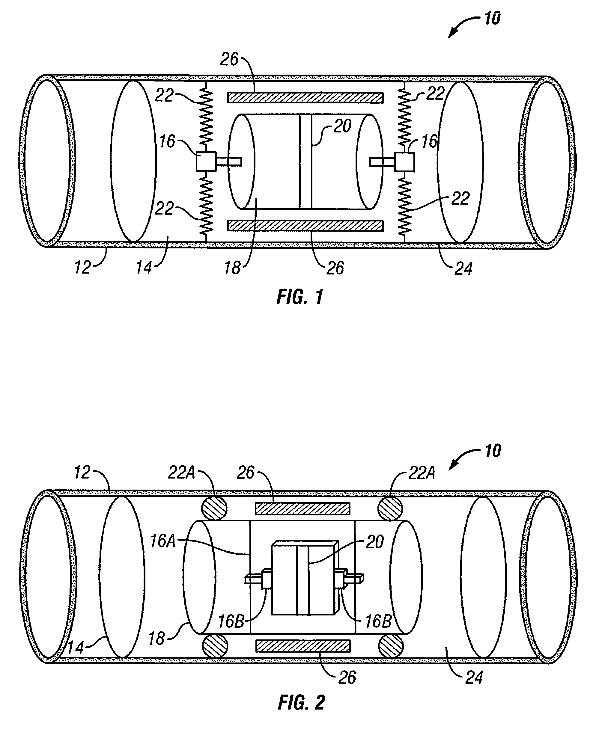
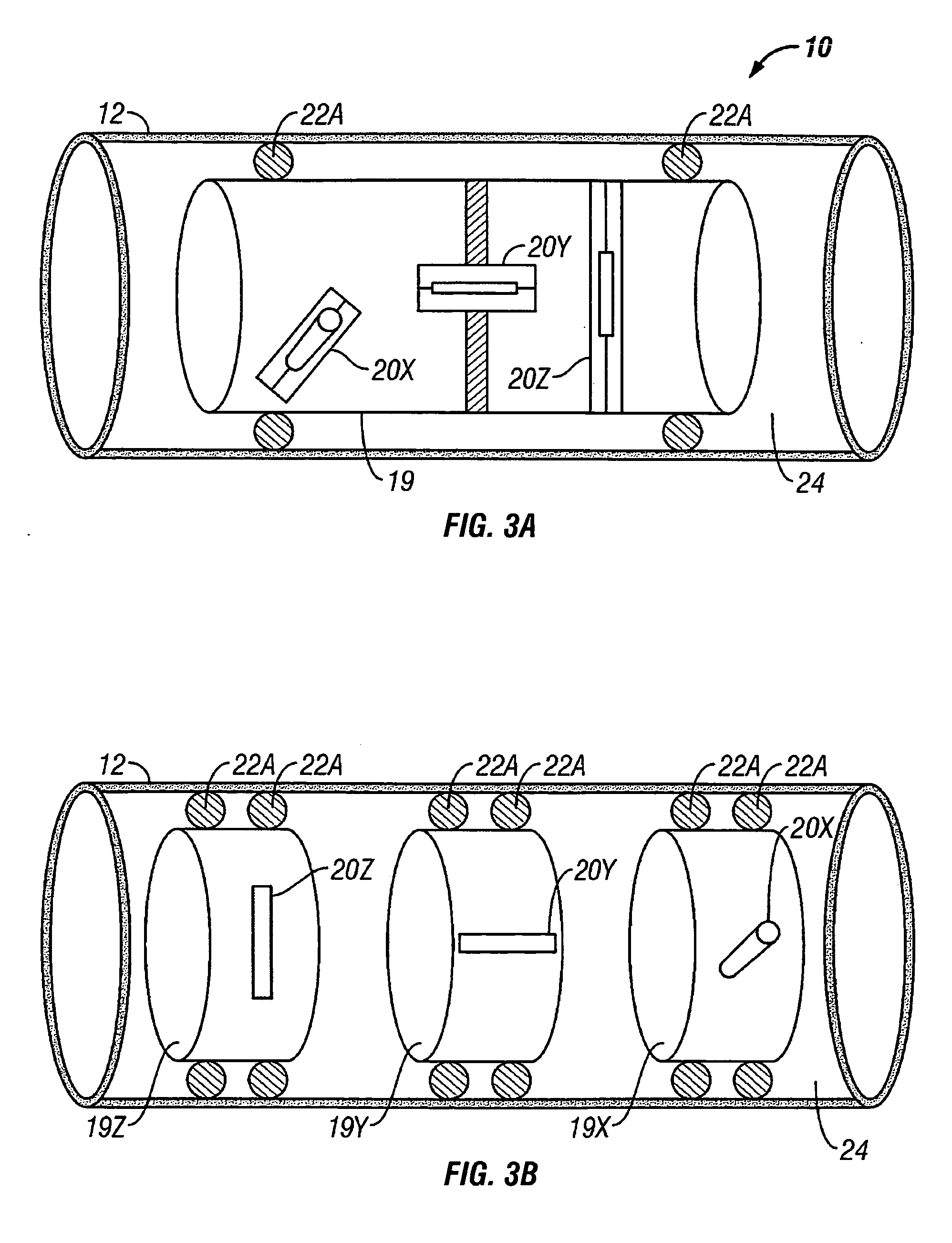
[0013]A marine seismic streamer according to one aspect of the invention includes a jacket substantially covering an exterior of the streamer. At least one strength member is disposed along the length of the jacket. A sensor mount is coupled to the strength member. At least one particle motion sensor is suspended within the sensor mount at a selected location along the jacket. The at least one particle motion sensor is suspended in the jacket by at least one biasing device. A mass of the particle motion sensor and a force rate of the biasing device are selected such that a resonant frequency of the particle motion sensor within the sensor jacket is within a predetermined range. The sensor mount is configured such that motion of the jacket, the sensor mount and the strength member is substantially isolated from the particle motion sensor.

Problems solved by technology

Such reverberations can have substantial amplitude within the total detected acoustic energy, masking the acoustic energy that is reflected from subsurface layer boundaries, and thus making it more difficult to infer subsurface structures and compositions from seismic data.
Motion of the streamer cable may include mechanically induced noise along the streamer cable, among other sources.
Such cable motion unrelated to seismic energy may result in noise in the output of the particle motion sensors which may make interpretation of the seismic signals difficult.

Method used


Image

  • Particle motion sensor mounting for marine seismic sensor streamers
  • Particle motion sensor mounting for marine seismic sensor streamers
  • Particle motion sensor mounting for marine seismic sensor streamers

Examples


Embodiment Construction

[0022]One example of a seismic sensor disposed in a section of a marine seismic sensor streamer is shown in cut away view in FIG. 1. The streamer 10 includes an exterior jacket 12 made of any material known in the art for enclosing components of a seismic sensor streamer, for example, polyurethane. The jacket 12 in the present example may include an integral strength member (not shown separately in FIG. 1 for clarity). Alternatively, the streamer 10 may include one or more separate strength members (see FIG. 3C) for transmitting axial load along the streamer 10. At least one sensor housing 14 is disposed inside the jacket 12 at a selected position along the jacket. Typical examples will include a plurality of such sensor housings disposed at spaced apart locations along the jacket 12. The sensor housing 14 may be formed from material such as plastic. In one example the plastic can be a type sold under the trademark LEXAN®, which is a registered trademark of General Electric Co., Fai...


PUM


Abstract

A marine seismic streamer includes a jacket substantially covering an exterior of the streamer. At least one strength member is disposed along the length of the jacket. A sensor mount is coupled to the strength member. At least one particle motion sensor is suspended within the sensor mount at a selected location along the jacket. The at least one particle motion sensor is suspended in the jacket by at least one biasing device. A mass of the particle motion sensor and a force rate of the biasing device are selected such that a resonant frequency of the particle motion sensor within the sensor jacket is within a predetermined range. The sensor mount is configured such that motion of the jacket, the sensor mount and the strength member is substantially isolated from the particle motion sensor.

Description

CROSS-REFERENCE TO RELATED APPLICATIONS [0001]Continuation in part of application Ser. No. 10 / 792,511 filed on Mar. 3, 2004.STATEMENT REGARDING FEDERALLY SPONSORED RESEARCH OR DEVELOPMENT [0002]Not applicable.BACKGROUND OF THE INVENTION [0003]1. Field of the Invention[0004]The invention relates generally to the field of seismic surveying systems and techniques. More specifically, the invention relates to arrangements for mounting particle motion sensors used with marine seismic streamers.[0005]2. Background Art[0006]In seismic exploration, seismic data are acquired by imparting acoustic energy into the earth near its surface, and detecting acoustic energy that is reflected from boundaries between different layers of subsurface earth formations. Acoustic energy is reflected when there is a difference in acoustic impedance between layers disposed on opposite sides of a boundary. Signals representing the detected acoustic energy are interpreted to infer structures of and composition of...

Claims


Application Information

Patent Timeline
Patent Type & Authority Applications(United States)
IPC IPC(8): G01V1/38
CPCG01V1/184G01V1/201G01V1/189
Inventor TENGHAMN, STIG RUNE LENNARTSTENZEL, ANDRE
Owner PGS AMERICA INC
Learn More