Display for multi-function key pad and electronic device having the same

a multi-functional, key pad technology, applied in the direction of instruments, cathode-ray tube indicators, computing, etc., can solve the problems of inconvenient use of mp3 function or camera function, and unsuitable key pad devices for recent electronic devices performing various and complicated functions. , to achieve the effect of minimizing power consumption, reducing user interface depth, and easy key operation

Active Publication Date: 2009-03-12
HYDIS TECH
View PDF7 Cites 15 Cited by
  • Summary
  • Abstract
  • Description
  • Claims
  • Application Information

AI Technical Summary

Benefits of technology

[0015]In addition, the display for a multi-function key pad and the electronic device having the same can provide a shallow user interface depth and easy key operation by variously changing and displaying characters, numbers, specific symbols, still images and moving images according to the user's choice.
[0016]In addition, the display for multi-function key pad and the electronic device having the same can keep images without continuous voltage supply and thus minimize power consumption due to bistable characteristic of the electrophoretic display panel.
[0017]In addition, the display for multi-function key pad and the electronic device having the same may further include a backlight at one side of the electrophoretic display panel, thereby easily providing various images even in the night without daylight.

Problems solved by technology

Therefore, the conventional key pad device has a disadvantage in that the key pad device is unsuitable for recent electronic devices performing various and complicated functions.
For example, it is difficult or impossible to input characters in global roaming of the mobile communication terminal because a predetermined character is fixedly allocated to each key.
In addition, there is another problem that it is inconvenient to use MP3 function or camera function because the user should operate keys in many times to use the functions in the mobile communication terminal.
In other words, a user interface depth is deep, and thus key operation is inconvenient and difficult.
However, the touch screen has a problem that instructions are not properly inputted, or the same instruction is repeatedly inputted in several times because the user cannot feel a sense of pressing the keys when the user touches or presses the keys.
Furthermore, when a key pad device is made of the touch screen, power is supplied to pixels formed on the entire touch screen, thereby increasing power consumption and manufacturing cost.

Method used


Image

  • Display for multi-function key pad and electronic device having the same
  • Display for multi-function key pad and electronic device having the same
  • Display for multi-function key pad and electronic device having the same

Examples


Embodiment Construction

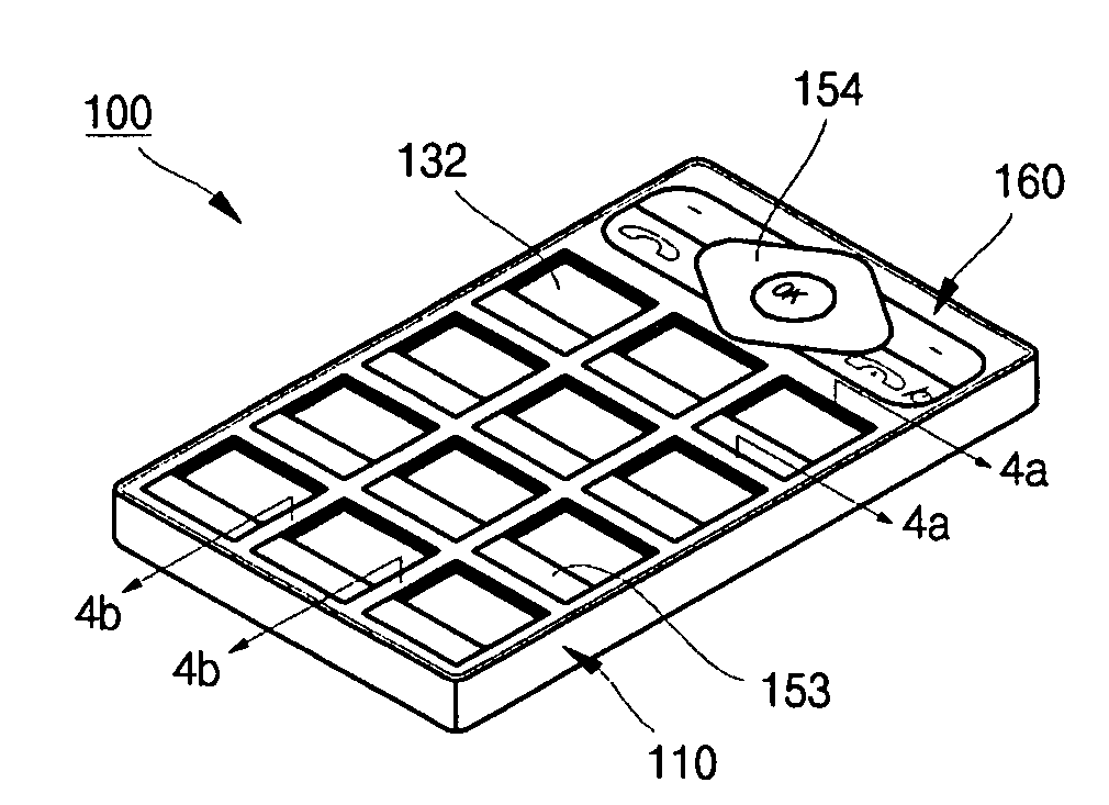
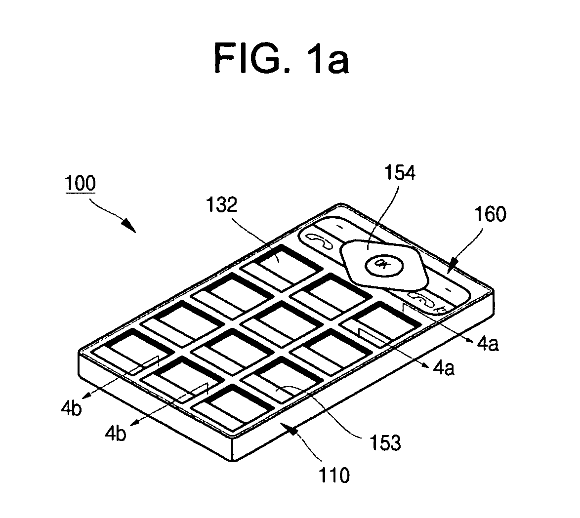
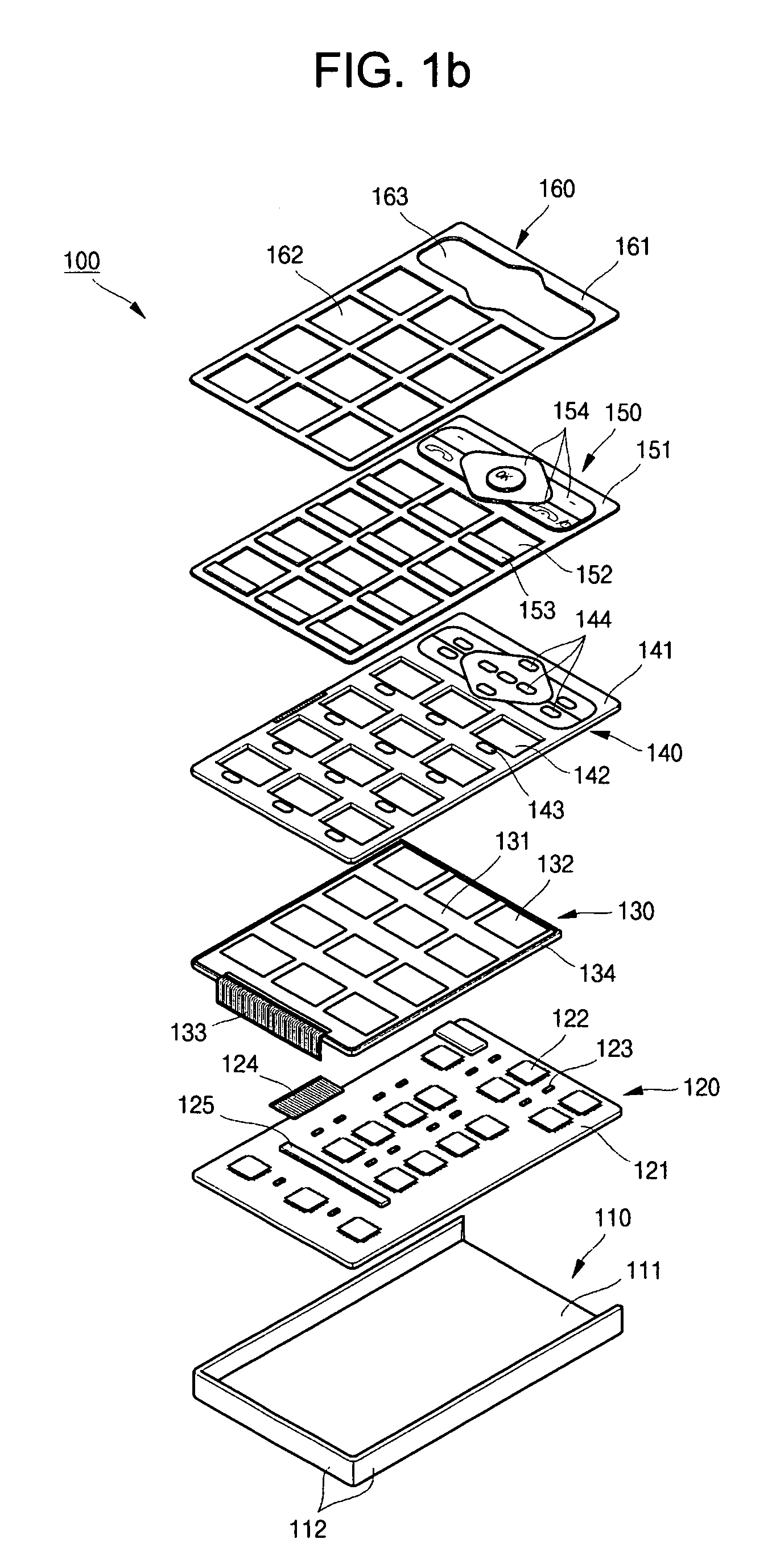
[0030]FIG. 1a shows a perspective view illustrating an assembled state of a display for a multi-function key pad according to one exemplary embodiment of the present invention, and FIG. 1b shows an exploded perspective view of FIG. 1a. Referring to FIGS. 1a and 1b, the display 100 for a multi-function key pad includes a case 110, a main circuit board 120 mounted on the case 110, an electrophoretic display panel 130 mounted on the main circuit board 120, a circuit board 140 mounted on the electrophoretic display panel 130, a pad 150 mounted on the circuit board 140, and a cover 160 mounted on the pad 150.

[0031]The case 110 includes a bottom surface 111, a plurality of side walls 112 formed in a predetermined height at a side part of an edge of the bottom surface 111. The case 110 may be formed of any one selected from a plastic resin, a metal and its equivalents, but not limited thereto. In addition, the main circuit board 120, the electrophoretic display panel 130, the circuit board...


PUM


Abstract

Disclosed are a display for a multi-function key pad and an electronic device having the display that have both input and output functions. The display for the multi-function key pad includes an electrophoretic display panel provided with a plurality of display regions arranged in a matrix form with having a non-display region as a boundary, a circuit board provided on the display panel and including a plurality of openings formed on regions corresponding to the display regions and a plurality of keys formed on regions that are outer circumference edges of the openings and correspond to the non-display region, and a pad provided on the circuit board and including a plurality of transparent windows formed on regions corresponding to the openings and a plurality of pressing units formed on regions that are outer circumference edges of the transparent windows and correspond to the keys.

Description

CLAIM FOR PRIORITY[0001]This application makes reference to, incorporates the same herein, and claims all benefits accruing under 35 U.S.C. §119 from an application earlier filed in the Korean Intellectual Property Office on 19 Apr. 2007 and there duly assigned Serial No. 10-2007-0038402.BACKGROUND OF THE INVENTION[0002]1. Field of the Invention[0003]The present invention relates to a display for multi-function key pad.[0004]2. Description of the Related Art[0005]Generally, electronic devices (for example, a mobile communication terminal) include a key pad device for inputting various instructions easily. For example, characters, numbers, or specific symbols have been previously allocated to each key of the key pad device. A user can properly perform various functions such as phone calling and receiving, character inputting, and message sending by operating the key pad.[0006]However, in the conventional key pad device, unique characters, numbers, or specific symbols have been alread...

Claims


Application Information

Patent Timeline
Patent Type & Authority Applications(United States)
IPC IPC(8): G06F3/02
CPCH01H13/83H04M1/23H01H2219/0023H01H13/70
Inventor KIM, KYONGDOJANG, HYUNAHNAMGUNG, HYUNGJUNLEE, WOOJONG
Owner HYDIS TECH
Why Eureka
Try Eureka