
Input display device, display control method and control program

a display device and control method technology, applied in the direction of instruments, computing, electric digital data processing, etc., can solve the problems of cumbersome user selection of the desired processing target on the display screen by using the cursor, and achieve the effect of simplifying the key operation for the user and enhancing the processing efficiency

Inactive Publication Date: 2008-04-17
SANYO ELECTRIC CO LTD
View PDF3 Cites 1 Cited by
  • Summary
  • Abstract
  • Description
  • Claims
  • Application Information

AI Technical Summary

Benefits of technology

[0010]Therefore, an object of the present invention is to provide an input display device, a display control method and a control program with which a cursor can be automatically moved to a next desired processing target candidate selectable position on a screen for selecting a processing target when the same processing is continuously executed on plural processing targets, thereby simplifying user's operation and enhancing the processing efficiency.
[0023]According to the present invention, when the same processing is sequentially executed on processing targets, on the basis of the processing target search / select record, the cursor shift record and the time interval between the subsequent operations, the controller can automatically shift the cursor to a selectable position of a next processing target candidate while estimating a user's intention of the cursor shift operation in advance, thereby simplifying the key operation for the user and enhancing the efficiency of the processing.

Problems solved by technology

That is, the user must shift the cursor to the desired processing target by pressing at least two key switches several times. Accordingly, the selecting work of the desired processing target on the display screen by using the cursor is cumbersome for users.

Method used


Image

  • Input display device, display control method and control program
  • Input display device, display control method and control program
  • Input display device, display control method and control program

Examples


Embodiment Construction

[0031]A preferred embodiment according to the present invention will be described hereunder with reference to the accompanying drawings.

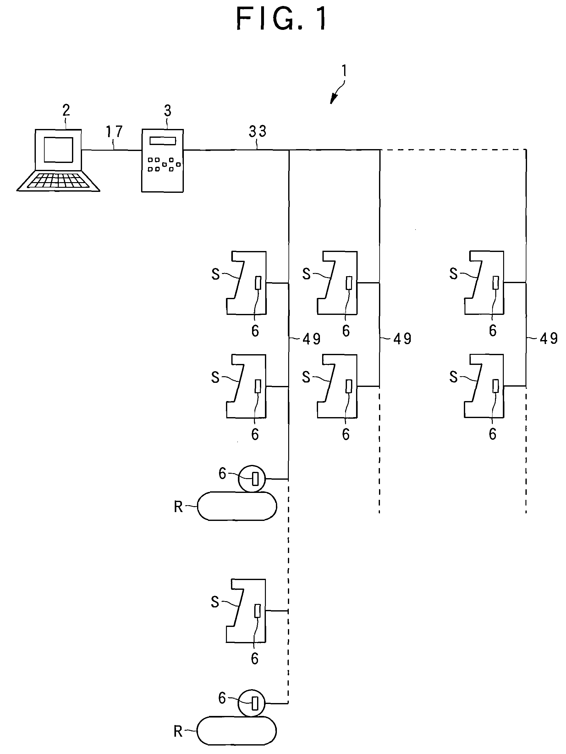
[0032]FIG. 1 is a diagram showing the construction of a central managing system according to an embodiment of the present invention.

[0033]The central managing system 1 is equipped with a central managing device 2 constructed as a personal computer, a main controller 3 constructed by a microcomputer, and terminal side controllers 6 provided to respective show cases, etc.

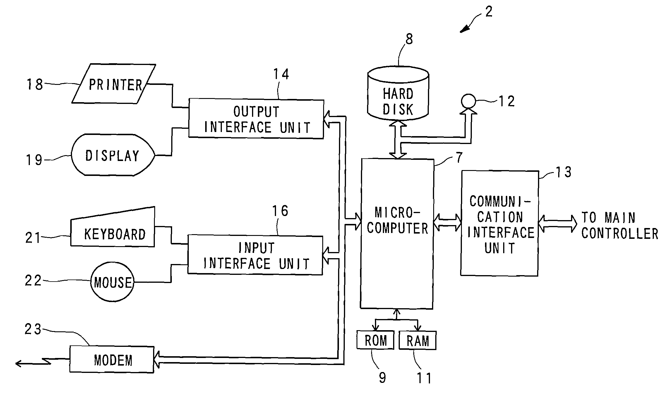
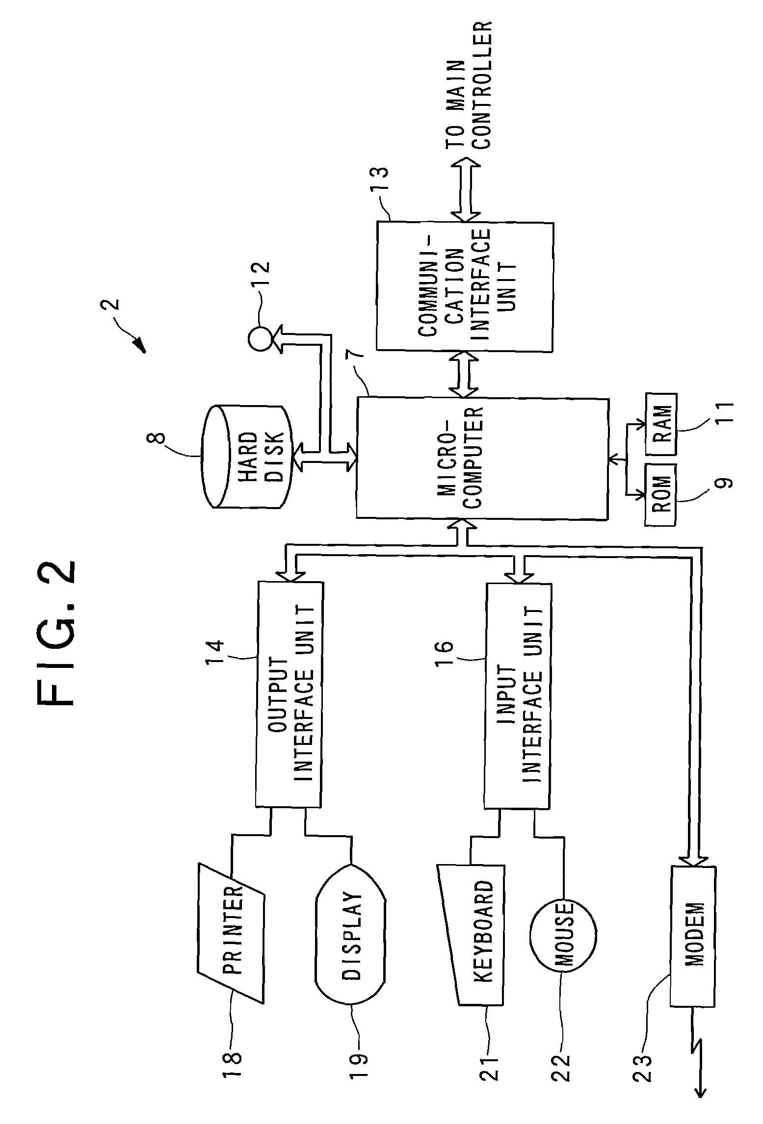
[0034]FIG. 2 is a block diagram showing the construction of the central managing device 2.

[0035]The central managing device 2 is provided in a security guards room or the like in a shop or the like, and it has a microcomputer 7 for controlling the whole of the central managing device 2 concerned, a hard disk (external storage device) 8 that is connected to the microcomputer 7, has a large storage capacity and stores various kinds of information, ROM 9 that is connected to the microcom...


PUM


Abstract

An input display device for enabling a user to input various kinds of information by using a cursor and displaying an input state on a display unit, including a memory for storing a processing target search / select record concerning selection of processing target candidates, and a cursor shift record concerning a cursor shift operation which is carried out on the display unit in connection with the selection of the processing target candidates, a timer for counting the time from a previous processing target search / select operation till a latest cursor shift operation, and a cursor shift controller for judging on the basis of the processing target search / select record, the cursor shift record and the time counted by the timer whether the latest cursor shift operation is carried out in connection with the same processing to be executed on processing targets, and allowing the cursor to shift to a selectable position of a next processing target candidate if it is judged that the latest cursor shift operation is carried out in connection with the same processing.

Description

INCORPORATION BY REFERENCE[0001]The present application claims priority under 35 U.S.C. §119 to Japanese Patent Application No. 2006-282243 filed on Oct. 17, 2006. The content of the application is incorporated herein by reference in its entirety.BACKGROUND OF THE INVENTION[0002]1. Field of the Invention[0003]The present invention relates to an input display device, a display control method and a control program, and particularly to an input display device, a display control method and a control program in an information processing device for selecting a data input position or a processing target by using a cursor.[0004]2. Background of the Invention[0005]A controller for concentrically controlling refrigeration apparatuses such as show cases, etc. is designed to collectively input set values required for the respective operations of a number of refrigeration apparatuses in a lump, thereby controlling the operation of each refrigeration apparatus (for example, see JP-A-1-291085).[00...

Claims


Application Information

Patent Timeline
Patent Type & Authority Applications(United States)
IPC IPC(8): G06F3/033
CPCG06F3/04892
Inventor KITA, MASANORIKAWAI, TSUYOSHI
Owner SANYO ELECTRIC CO LTD
Learn More