
Dirt Scraper for a Disc Brake
a disc brake and dirt scraper technology, applied in the direction of brake types, braking elements, braking members, etc., can solve the problems of disc wear, reduced braking effect, grinding,
- Summary
- Abstract
- Description
- Claims
- Application Information
AI Technical Summary
Benefits of technology
Problems solved by technology
Method used
Image

Examples
Embodiment Construction
[0033]The embodiments of the invention with further developments described in the following are to be regarded only as examples and are in no way to limit the scope of the protection provided by the patent claims.
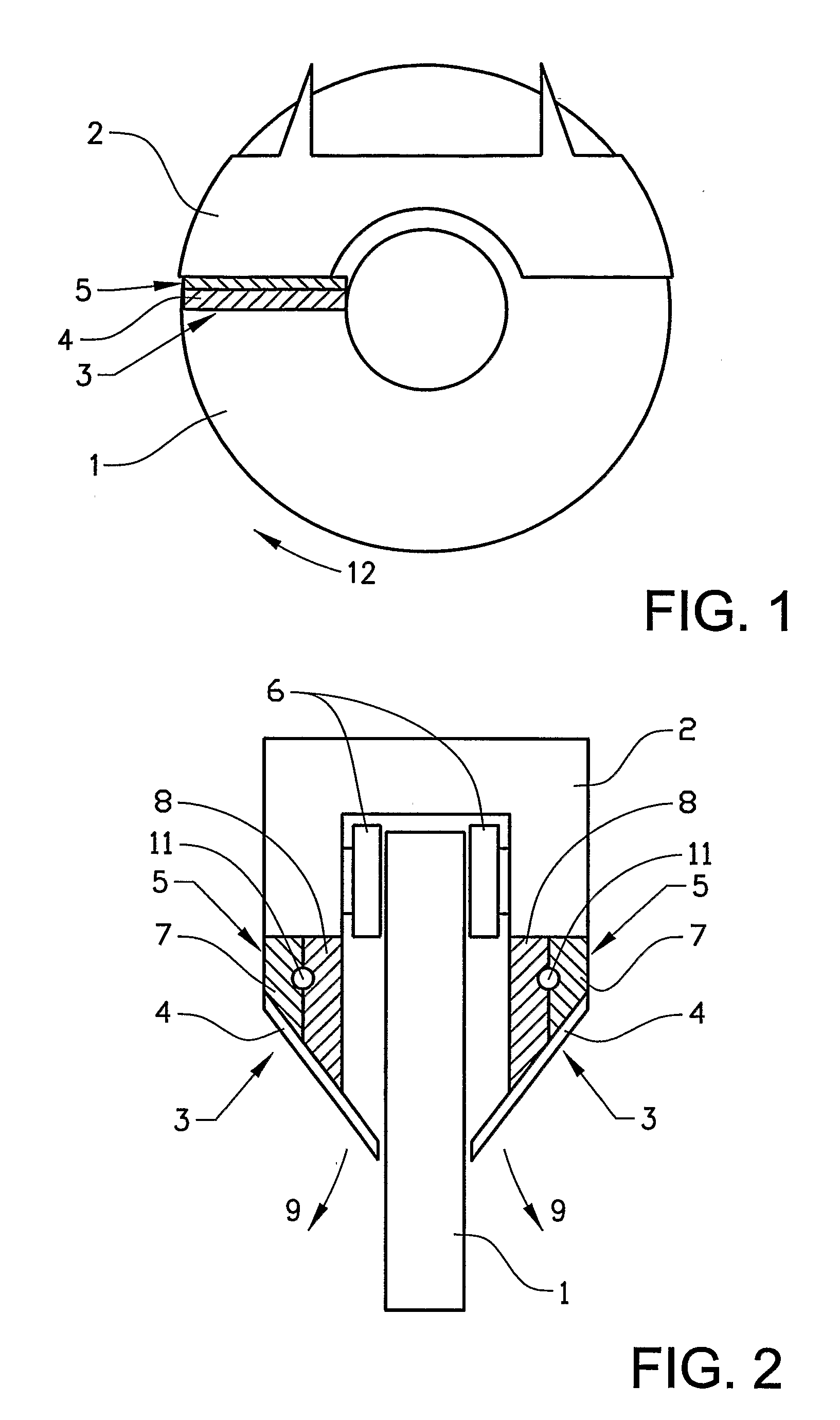
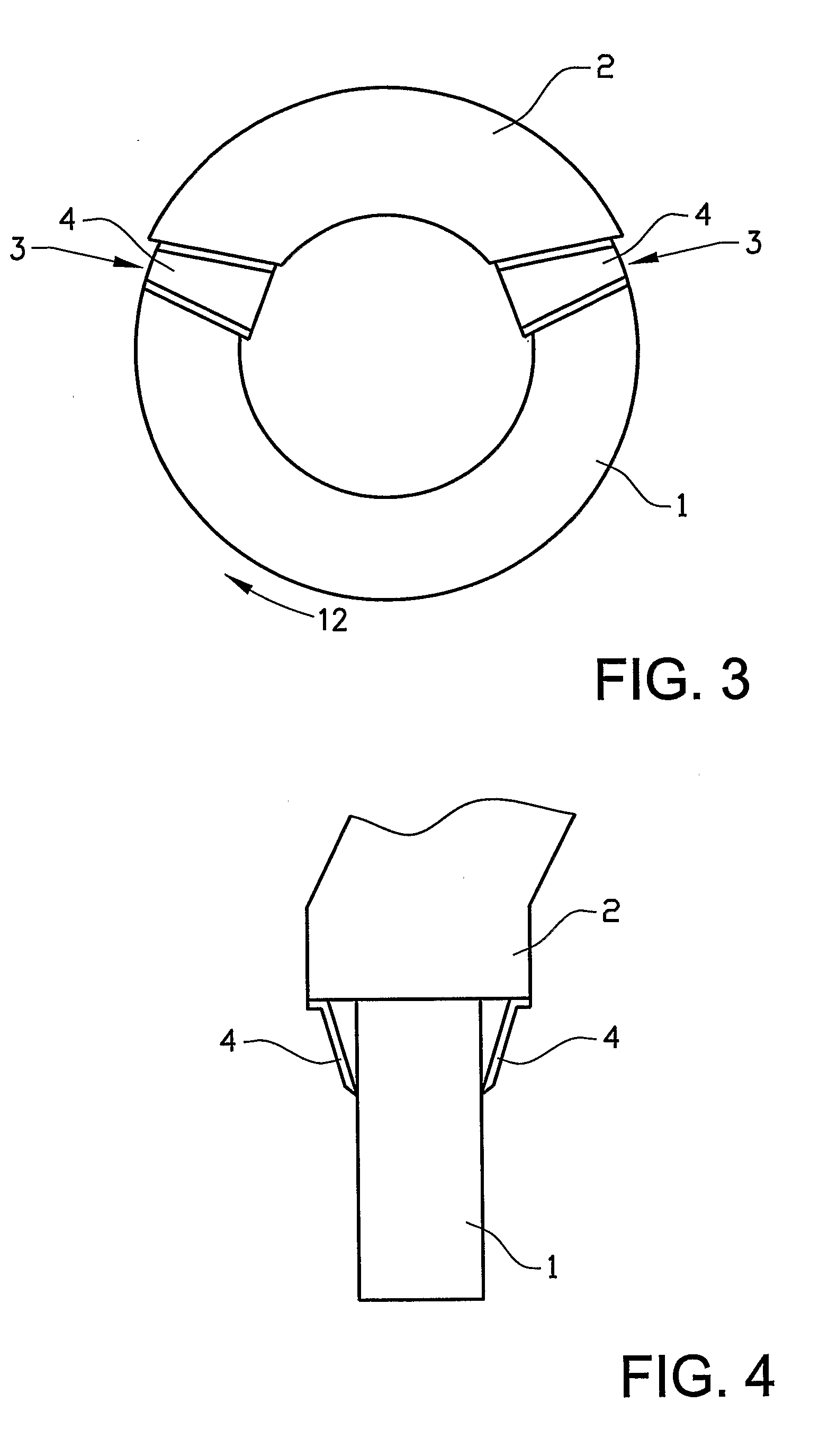
[0034]FIG. 1 shows a disc brake comprising a disc 1 and a brake calliper 2. The dirt scraper 3 is attached to the vehicle (not shown) and comprises a scraper blade 4 and a heat-sensing element in the form of a bimetallic element 5. The bimetallic element is attached to the stationary brake calliper 2. The disc 1 is moving in the direction 12.
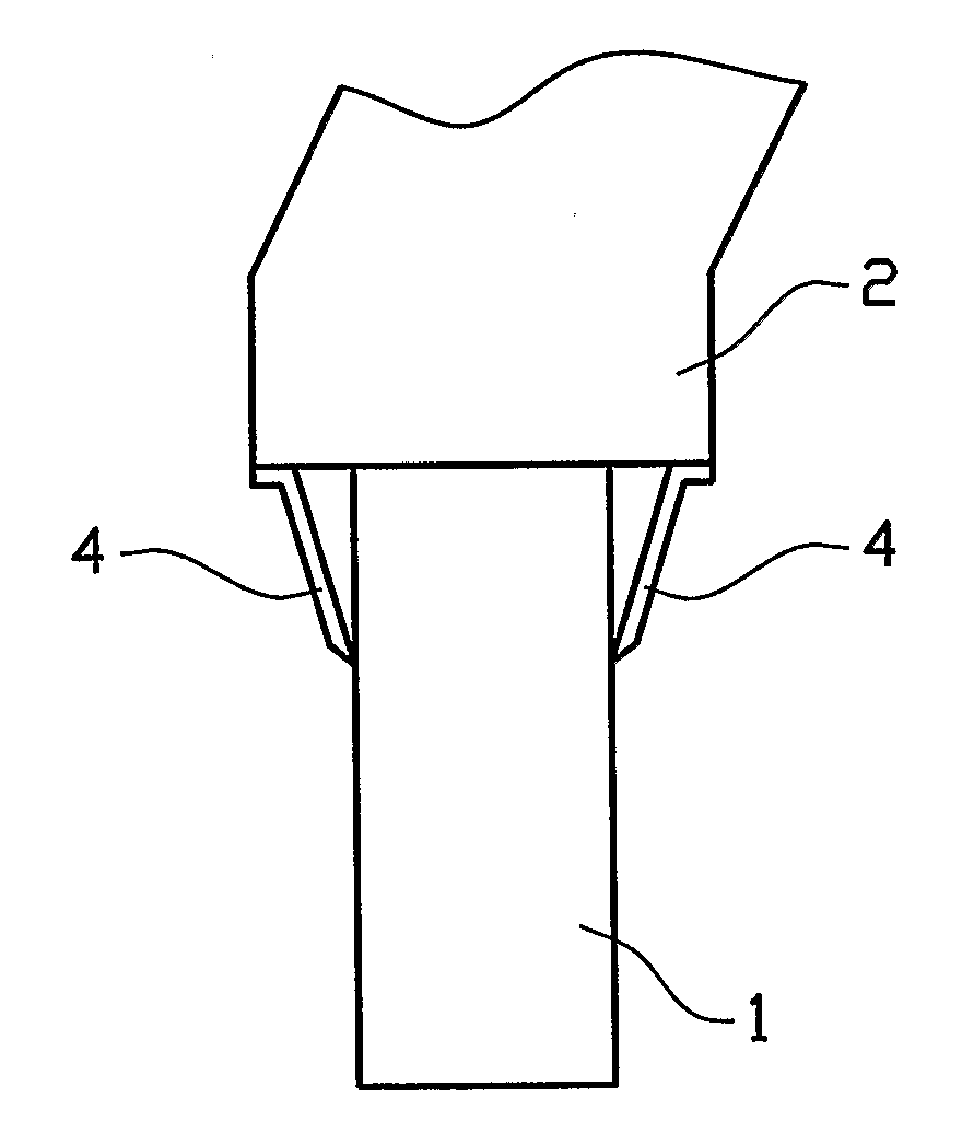
[0035]FIG. 2 shows a front view of disc brake comprising a brake calliper 2 and two brake pads 6 to be pressed towards the disc 1 for obtaining a braking effect. Two dirt scrapers 3 are attached to the brake calliper 2, one on each side, and comprise a bimetallic element 5 consisting of two metals 7, 8 having different coefficient of thermal expansion and a scraper blade 4 mounted to the bimetallic element 5. The bimetallic element also...
PUM
 Abstract
Description
Claims
Application Information