Document dispensing apparatus

a technology for dispensing equipment and documents, applied in the direction of transportation and packaging, thin material handling, article separation, etc., can solve the problems of high cost of document separators, complex equipment, and relatively rapid wear and tear of documents

Inactive Publication Date: 2002-08-27
TALARIS LTD
View PDF11 Cites 4 Cited by
  • Summary
  • Abstract
  • Description
  • Claims
  • Application Information

AI Technical Summary

Benefits of technology

With this invention, the separation system has a much simpler construction than the prior art and is highly reliable while achieving even wear on the "other" roller.
Preferably, the coefficient friction of the one roller is higher than that of the other roller. This enhances the separation process carried out by the separation system.
Conveniently, the apparatus further comprises a conveyor which receives a document passing between the pair of rollers, and which conveys the document at an elevated speed; a sensor for detecting the presence of a document at the inlet to the conveyor; and a control unit, the sensor being adapted to cause the control unit to influence the current supply to the drive motor when detecting the leading edge of said document, so as to reduce braking of a document passing through the roller pair and having entered the conveyor, to a selected level.
In the preferred arrangement, the drive motor may also be adapted to drive the feed roller. When the sensor detects that a document has been fed into the conveyor, it causes a computer connected thereto to change the supply of current to the motor so as to reduce the braking effect of the roller pair on the document. The conveyor engages a document before the document has left the roller nip, whereby the document is braked by virtue of the conveyor speed being greater than the conveying speed of the roller pair. When the sensor later detects the trailing edge of the document, the computer is caused to drive the motor in the reverse direction for a short period of time, for instance for some milliseconds. The second transmission then jogs the second roller of said roller pair into rotation, preferably in a direction which is opposite to the direction in which the document passes through the roller nip. Consequently, after each separation operation, the second roller of the roller pair will rotate to advance a fresh peripheral section for coaction with a document and the barrel surface of the first roller of said roller pair respectively.

Problems solved by technology

One problem with arrangements of this kind is that the document separator is expensive, complex and wears relatively quickly.

Method used


Image

  • Document dispensing apparatus
  • Document dispensing apparatus
  • Document dispensing apparatus

Examples


Embodiment Construction

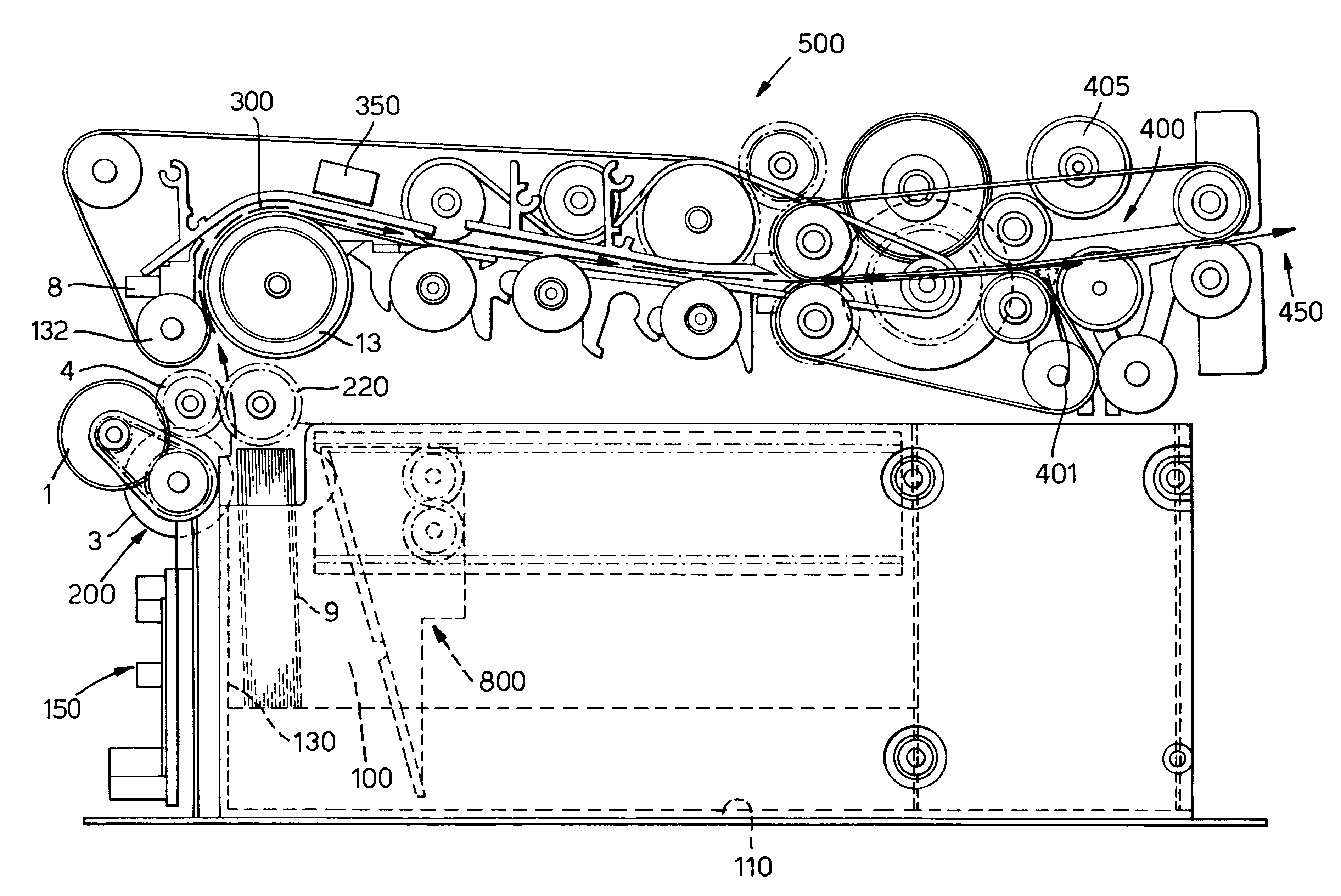
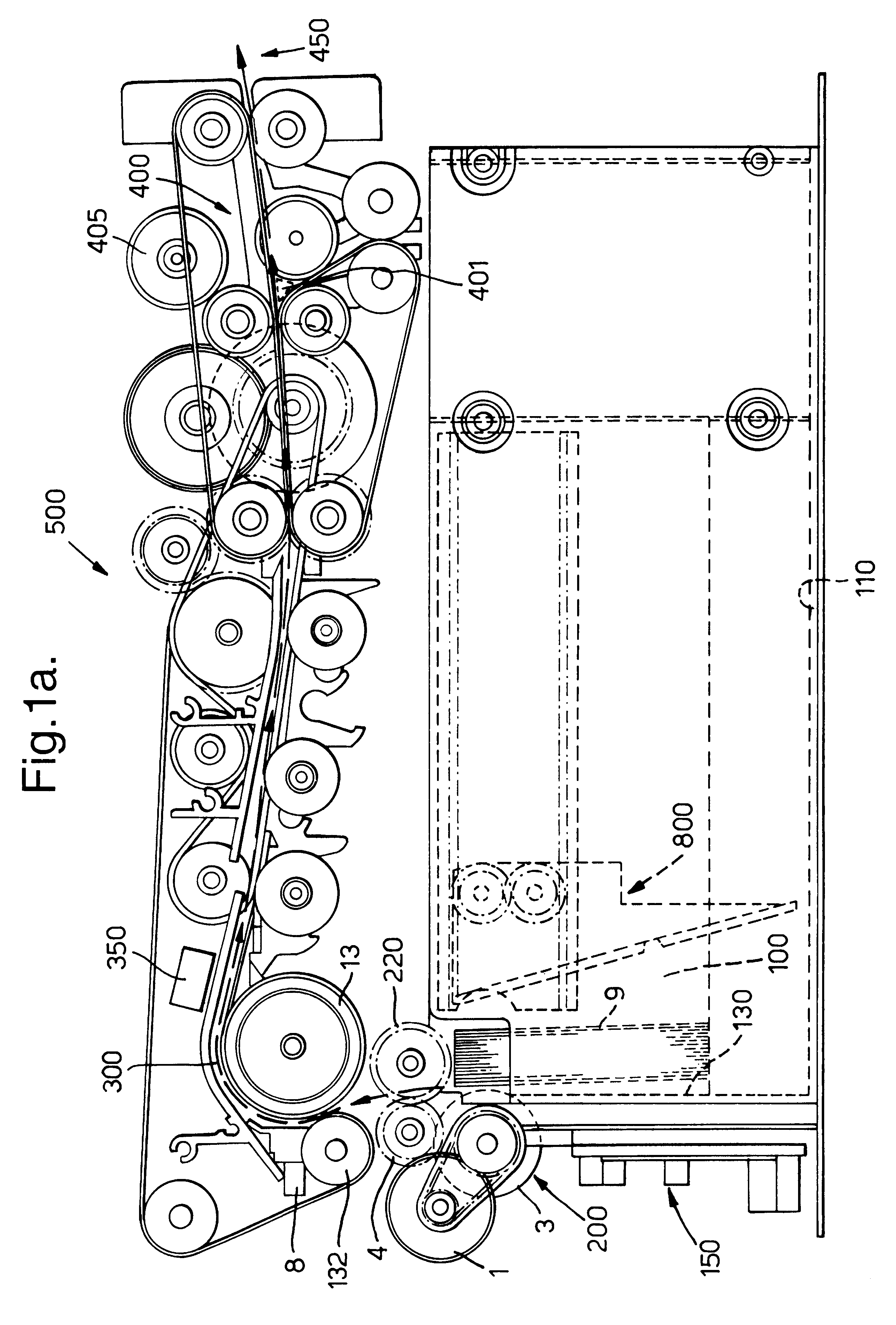
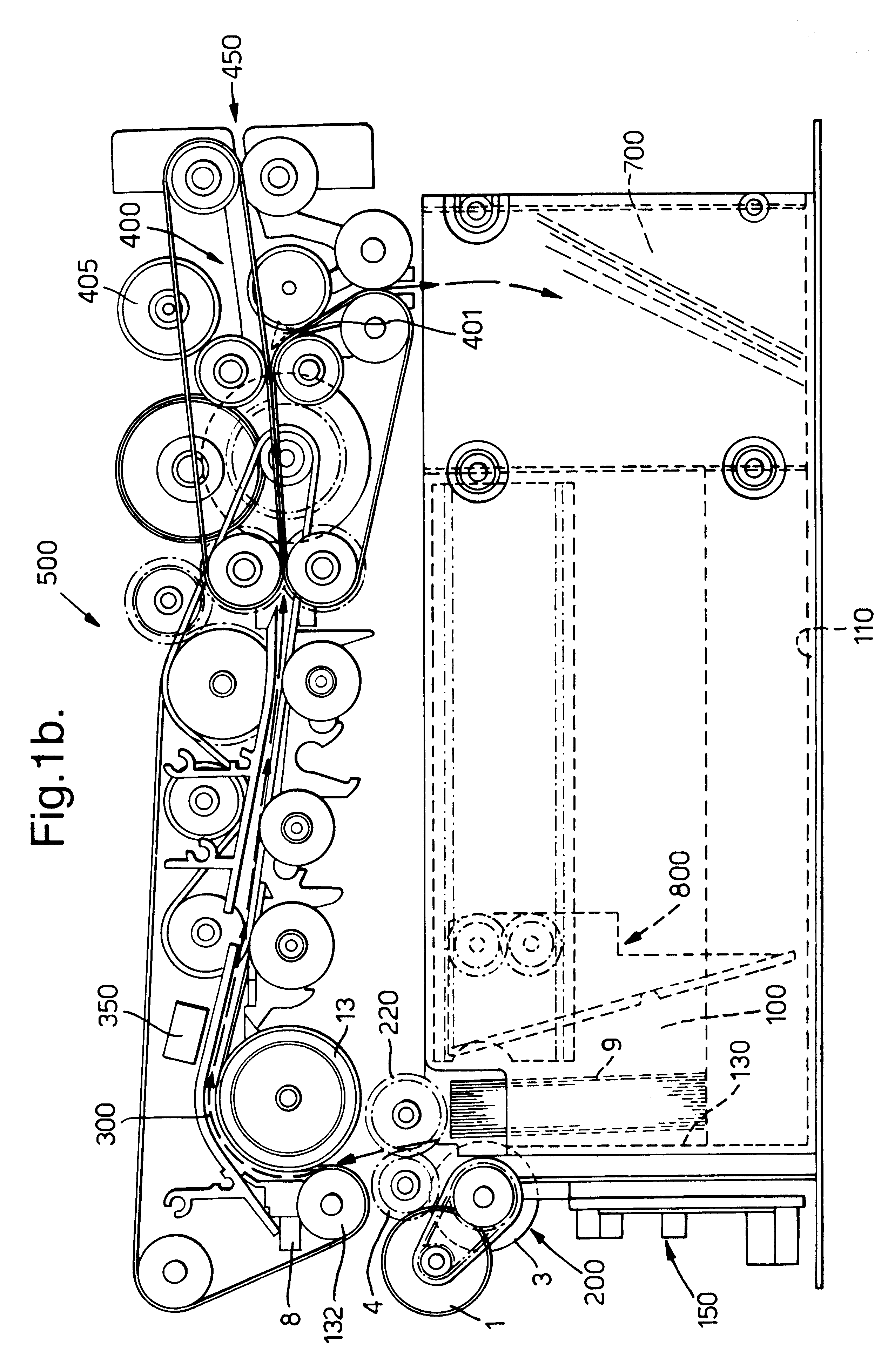
As is shown in the drawings, a note and media dispensing apparatus 500 has a note compartment 100 defined by a base 110, side walls 120 and a front wall 130, in which notes 9 are pushed by a spring loaded device 800 against pick rollers 3 of a note feeding and separating mechanism 200. The note compartment 100 has known adjustable features, which are set to suit the chosen note size. Notes are fed one by one and separated by the note feed and separating mechanism 200 and fed into a note transport path 300.

The note feed and separating mechanism 200, FIG. 2a, consists of two pick rollers 3 arranged non-rotatably on a common shaft 31 to which a toothed pulley 201 is non-rotatably mounted, pulley 201 being connected by a toothed belt 202 to a toothed pulley 203 non-rotatably mounted to a shaft 41 to which a feed roller 4 is non-rotatably mounted. Toothed pulley 204 is also connected via a toothed belt 205 and pulley 206 to the drive shaft of a motor 1.

Shaft 31 and 41 are rotatably mount...


PUM


Abstract

An arrangement for feeding documents piecemeal from a document bundle (9) comprises a banknote separator (200) which includes two mutually biased rollers (4,6) that are driven by a drive motor (1) that also drives a dispensing roller (3) which functions to dispense documents from the bundle. The rollers (4,6) of the roll pair are rotationally coupled together via a freewheeling hub. The second roller (6) does not rotate during dispensing of a document. Upon completion of a dispensing operation, the drive direction of the motor (1) is reversed, so as to bring the second roller (6) to a new angular position.

Description

The present invention relates to apparatus for dispensing documents such as banknotes or other documents of value piecemeal from a bundle of documents.DESCRIPTION OF THE PRIOR ARTKnown such apparatus comprises a bundle holder that includes a slide surface on which the bundle rests and is displaced forwards, a front wall, a pusher which pushes the bundle along the slide surface and into contact with the front wall, a dispensing roll of which a peripheral part is in contact with the foremost document in the bundle, drive means for selective rotation of the dispensing roll in a first direction, for dispensing said foremost document in the bundle in the plane of said document, a pair of rolls that have mutually parallel axles and that are adapted so that their barrel surfaces act on respective opposite sides of a document dispensed into the nip defined by said roll pair, wherein the rolls of said roll pair are rotated at different peripheral speeds so as to mutually separate any documen...

Claims


Application Information

Patent Timeline
Patent Type & Authority Patents(United States)
IPC IPC(8): B65H3/52
CPCB65H3/5246B65H2403/72B65H2403/942B65H2404/531B65H2513/41B65H2513/51B65H2220/02B65H2220/01B65H2701/1912
Inventor ANDERSSON, JORGENHORPU, TERUNORDIN, ANDERS
Owner TALARIS LTD
Why Eureka
Try Eureka