Roller skate braking system

a braking system and roller skate technology, applied in the field of roller skates, can solve the problems of user risk, user is not optimal, risk of falling, etc., and achieve the effect of reducing the effectiveness of braking, avoiding any forward unbalance, and self-control of braking

Active Publication Date: 2011-04-19
DECATHLON SA
View PDF8 Cites 4 Cited by
  • Summary
  • Abstract
  • Description
  • Claims
  • Application Information

AI Technical Summary

Benefits of technology

[0007]As such, the invention relates to a roller blade, also called roller skate, providing self-control of the braking; when the skater topples forwards, the pressure exerted at his / her heel decreases thereby reducing the effectiveness of the braking and avoiding any forward unbalance.
[0010]Thus, the triggering device is capable of being actuated under the action of the actuation device for passing from a position for blocking the plate during skating and to a position for unblocking the latter during braking allowing the fixed portion to move closer to the mobile portion in order to cause the rolling system to come into contact with the braking component. Such a design has the advantage of avoiding untimely and involuntary braking actions while practicing skating. Moreover, the pressure exerted by the weight of the skater and his / her inertia on the rear of the roller blade allows the mobile portion to move closer to the fixed portion and thus causing the rolling system to contact the braking component. The pressure is consequently more or less significant depending on the weight and on the inertia of the skater.
[0014]According to a first embodiment, the actuation device consists of a rod which includes at least two portions jointed to one another, notably at the ankle bone level, along a transverse pivot axis. The first portion surrounds at least the heel of the foot positioned inside a piece of footwear. Additionally, the second portion surrounds at least the lower portion of the calf; the pivoting of the second portion of the rod, by action of the leg, allows the calf to be supported on the second portion, actuating the connecting rod.

Problems solved by technology

Such a braking system has a risk for the user, notably when the latter cannot control braking, and in particular the movement of his / her leg actuating said second portion of the rod which acts on said braking system.
The stability of the user is then not optimum, the latter may topple forwards; consequently there is a risk of falling.
Such a roller blade design may cause untimely braking when the user involuntarily presses on the rear of the plate, or when the road on which the user skates is more or less deformed or bumped, tending to involuntarily bring the mobile portion closer to the fixed portion.

Method used


Image

  • Roller skate braking system
  • Roller skate braking system
  • Roller skate braking system

Examples


Embodiment Construction

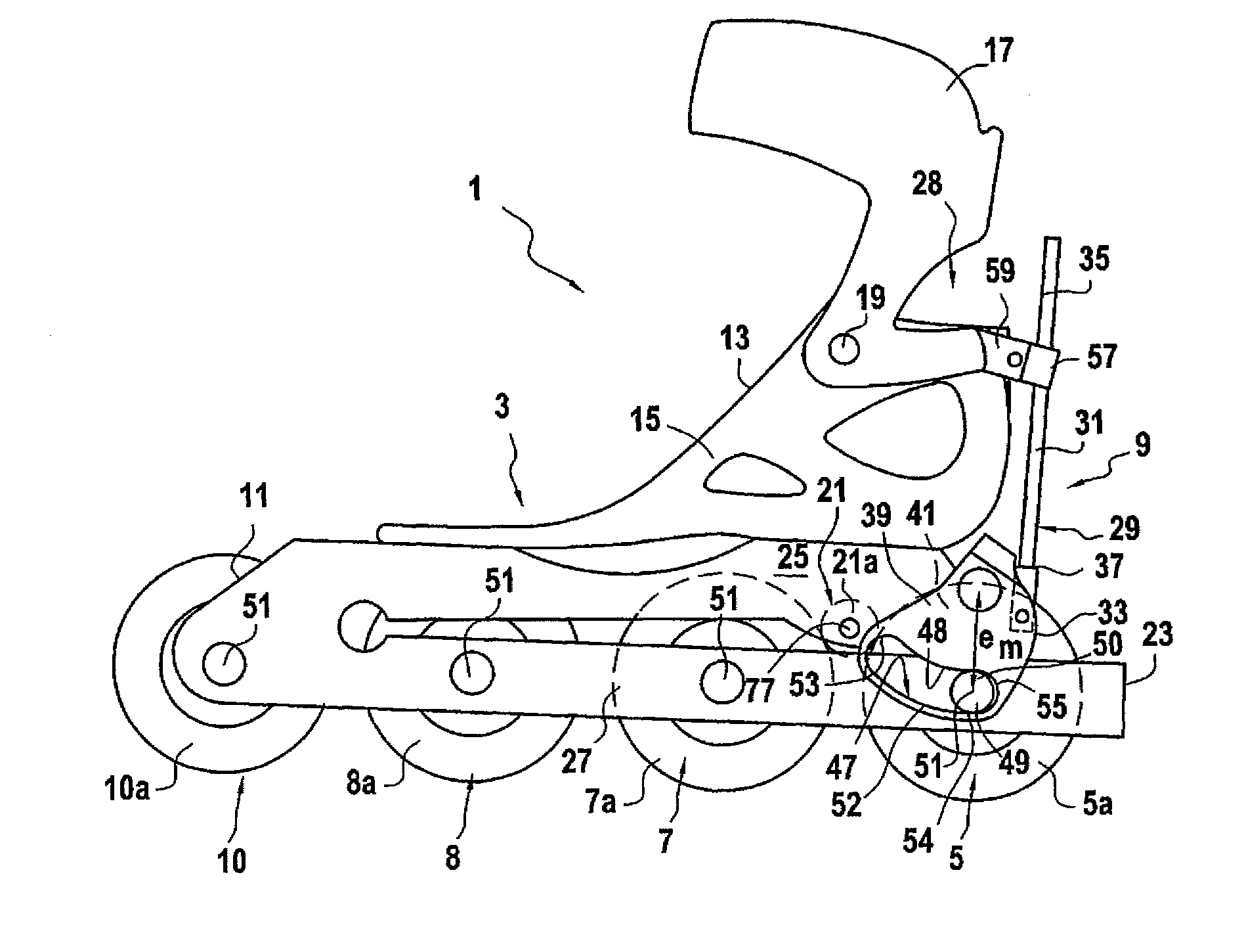
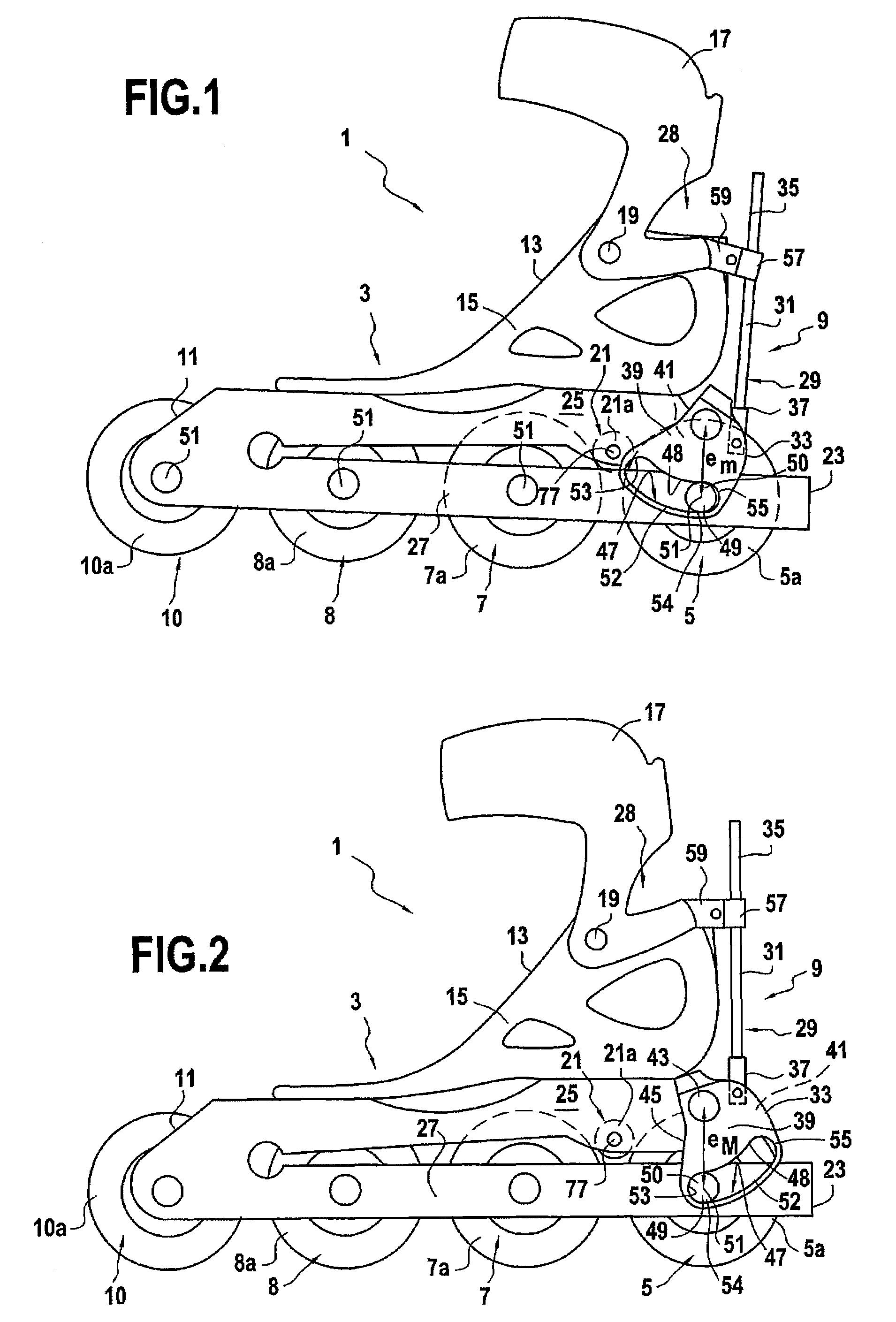
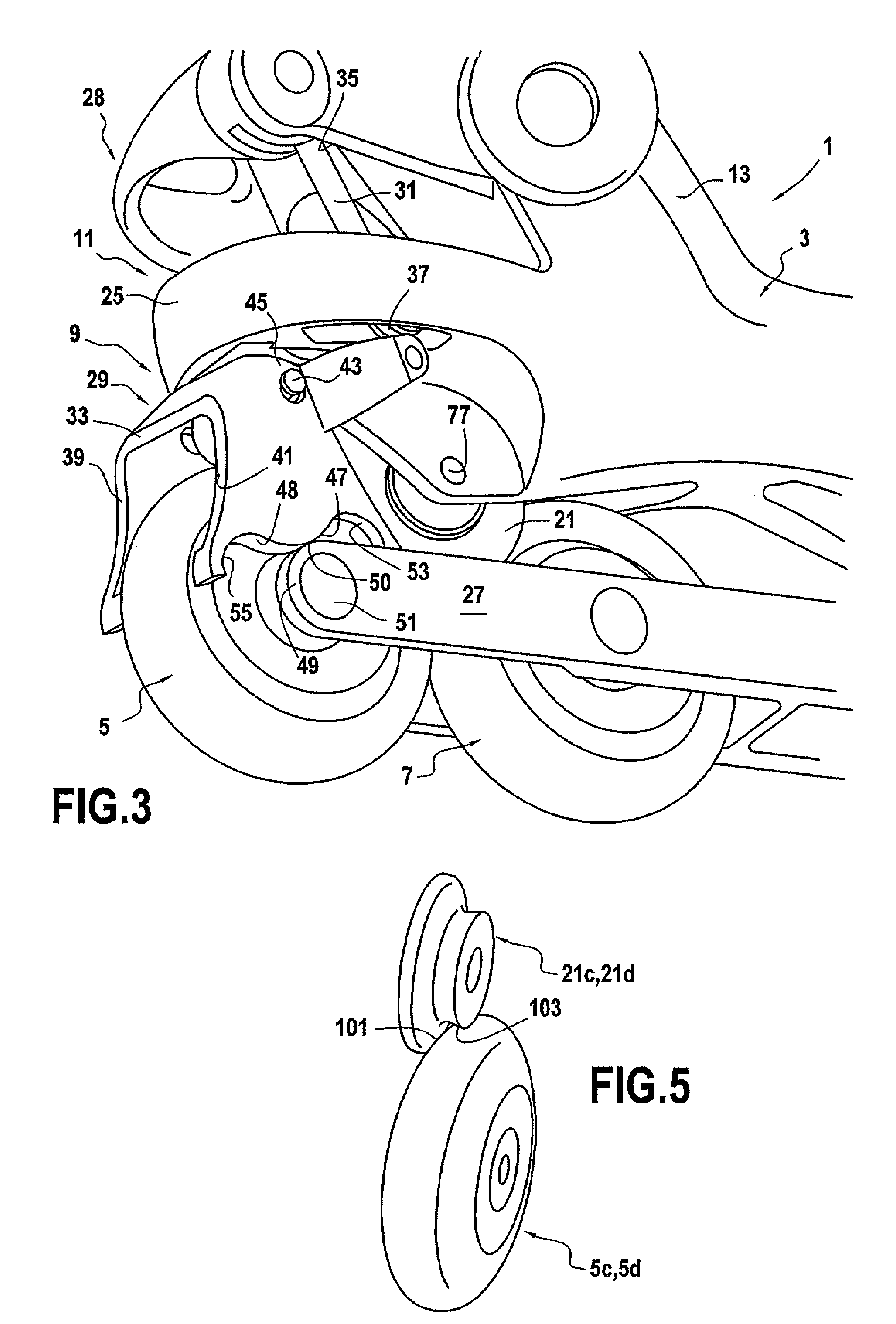
[0022]According to the different design embodiments of the present invention, as illustrated in FIGS. 1-4, the roller blade 1 is equipped with a frame 3 which comprises a longitudinal plate 11. This longitudinal plate 11 consists of two portions 25, 27; the first portion 25 is said to be “fixed” in the following description, while the second portion 27 is said to be “mobile”. However said first portion 25 may be considered as mobile and said second portion 27 as fixed.

[0023]According to the design embodiment illustrated in FIGS. 1 and 2, the longitudinal plate 11 is slit over a portion of its length, from its rear end 23. With such a slit on the plate 11, it is possible to form the fixed portion 25 and the mobile portion 27. Additionally, the material selected for making the plate 11 notably designed in a composite material, allows elastic deformation of said plate 11 in order to allow the fixed portion 25 and mobile portion 27 to move closer to each other. This slit is preferably m...


PUM


Abstract

A roller blade having a frame, at least two rolling systems and a braking system. The frame has a plate on which the rolling systems and a foot blocking device are mounted in line. The braking device includes a braking component. The plate has two portions, one of which, a so-called fixed portion, receives the braking component, and the other one, a so-called mobile portion, receives at least one of the rolling systems positioned under the braking component in order to come into contact with the latter and slow it down when the mobile plate moves closer to the fixed portion. The roller has an actuation device of the braking system arranged on the frame so as to be notably controlled with the foot or leg of the user, the braking system having a triggering device capable of being actuated under the action of the actuation device for passing from a position for blocking the plate during skating, to a position for unblocking the latter during braking allowing both fixed and mobile portions to move closer to each other.

Description

FIELD OF THE INVENTION[0001]The invention relates to an in-line roller blade equipped with a braking system. It will find its application in an industrial environment, at sports equipment manufacturers, notably manufacturers of roller blades, and will most particularly be marketed in sales areas for sports equipment.BACKGROUND OF THE INVENTION[0002]Two types of rollers blade are notably known, i.e. in-line roller blades consisting of three or four wheels positioned in a line behind each other, and roller blades, more commonly called roller skates, of the “quad” type, i.e. consisting of two transverse axes of rotation, one positioned upstream and the other downstream from the roller blade, each axis receiving a wheel at both of its ends. Additionally, depending on these types of roller blades, the latter comprise a frame consisting of a longitudinal plate on which rolling systems are mounted in line, i.e. the wheels, or even pairs of wheels are positioned in line. Additionally, the f...

Claims


Application Information

Patent Timeline
Patent Type & Authority Patents(United States)
IPC IPC(8): A63C17/14
CPCA63C17/065A63C17/1418A63C2017/1481
Inventor QUENDEZ, NICOLAS
Owner DECATHLON SA
Why Eureka
Try Eureka