Method for detecting the ambient pressure in an internal combustion engine

a technology of ambient pressure and internal combustion engine, which is applied in the direction of machines/engines, electric control, instruments, etc., can solve the problems of unsatisfactory change in the operating state of the internal combustion engine, and achieve the reduction of the braking effect preventing an increase in and reducing the torque of the internal combustion engine

Active Publication Date: 2009-12-08
VITESCO TECH GERMANY GMBH
View PDF17 Cites 4 Cited by
  • Summary
  • Abstract
  • Description
  • Claims
  • Application Information

AI Technical Summary

Benefits of technology

[0008]The inventive method makes possible a more exact determination of the ambient pressure with the aid of the pressure sensor in the intake pipe by comparison with prior art methods. This is based on the known pressure conditions in the intake pipe, i.e. the ambient pressure is equal to the total of the sub-pressures at the throttle flap, the air cleaner and in the intake pipe collector. To enable the ambient pressure to be determined from the measured values of the pressure sensor in the intake pipe collector, the internal combustion engine is dethrottled far enough, i.e. the throttle flap is opened wide enough for the drop in pressure at the throttle flap to become negligibly small. This method is executed in the widest variety of operating states of the internal combustion engine, i.e. in the part-load, full-load and overrun mode of the internal combustion engine. The dethrottling of the internal combustion engine however leads to an undesired change in the operating state of the internal combustion engine. Thus for example in part load mode a higher torque would be created by the internal combustion engine by the dethrottling. In overrun mode in its turn the dethrottling leads to a reduced braking effect of the internal combustion engine. To prevent this undesired operating state of the internal combustion engine or at least to minimize it far enough for it not to be noticeable to the driver, the opening of the throttle flap is compensated for by an adjustment of the camshaft depending on the operating state of the internal combustion engine.
[0009]To this end, in part-load or full-load operation of the internal combustion engine for example, the camshaft, especially the inlet camshaft(s), is or are adjusted to “early” in order to prevent an increase in the torque of the internal combustion engine through the dethrottling. To enable the change in the operating state through dethrottling of the internal combustion engine to be prevented even more effectively, the ambient pressure is preferably only defined in operating states of the internal combustion engine which can be implemented with a small valve lift. To supplement this the camshaft is adjusted to a “small valve lift” in order to minimize the influence of the dethrottling on the operating state.

Problems solved by technology

The dethrottling of the internal combustion engine however leads to an undesired change in the operating state of the internal combustion engine.

Method used


Image

  • Method for detecting the ambient pressure in an internal combustion engine
  • Method for detecting the ambient pressure in an internal combustion engine
  • Method for detecting the ambient pressure in an internal combustion engine

Examples


Embodiment Construction

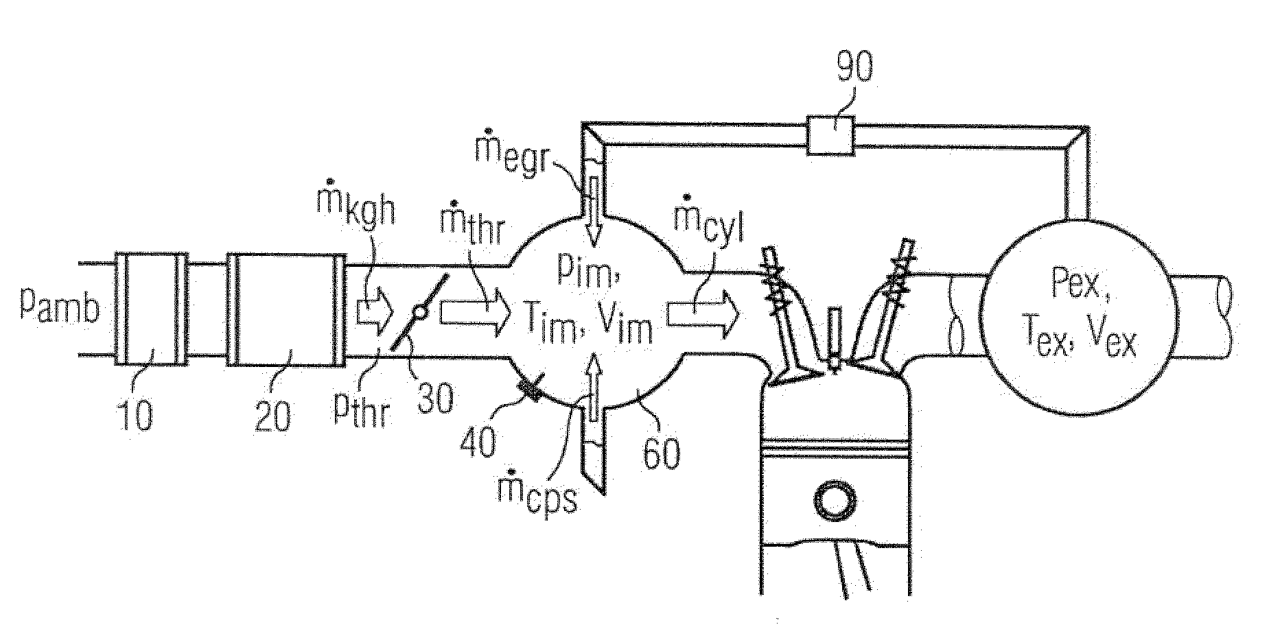
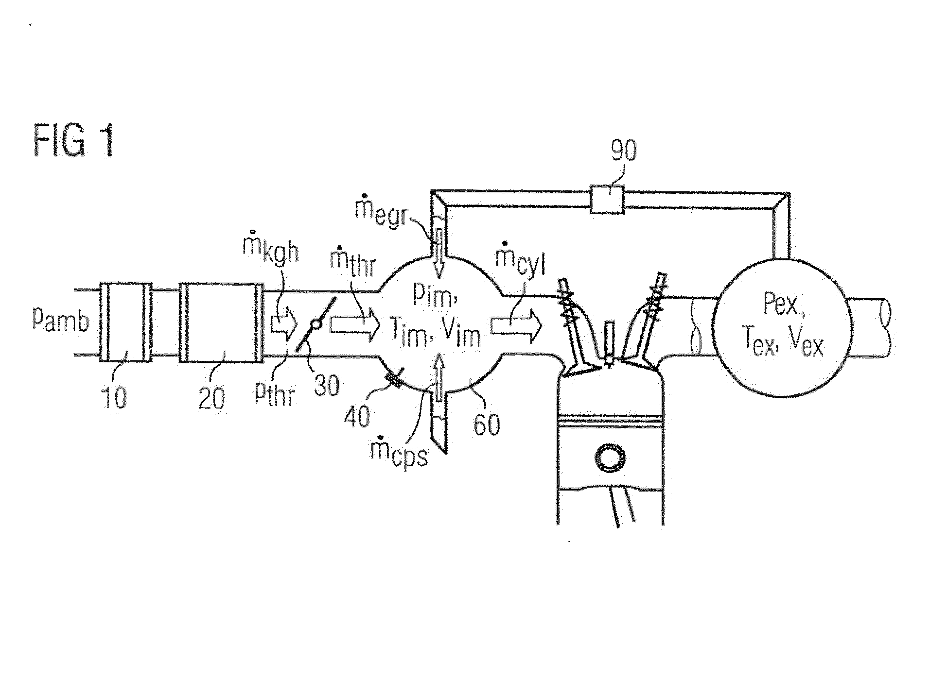
[0016]FIG. 1 shows the intake pipe model an internal combustion engine without a supercharger. The air at the ambient pressure pamb flows on induction via the air cleaner 10 through the air mass meter 20 via the throttle flap 30 into the intake pipe collector 60. In addition an air mass megr can be introduced through a valve 90 via the exhaust gas recirculation. It is likewise possible for the tank leakage diagnosis pump to feed a fuel / air mixture with the mass mcps to the intake pipe collector.

[0017]The intake manifold pressure pim and the intake temperature Tim is detected in the intake pipe for example with a combined pressure-temperature sensor. In the normal case either an intake pipe pressure sensor 40 and / or an air mass sensor 20 is or are built into the intake pipe of the internal combustion engine.

[0018]For the case of an opened throttle flap 30 a value is set as the intake manifold pressure pim which can be described by the ambient pressure Pamb as well as by the drop in p...


PUM


Abstract

There is described a method for detecting the ambient pressure by a pressure sensor in the intake pipe of an internal combustion engine. A throttle flap is opened so that the pressure drop via the throttle flap can be neglected. The dethrottling of the internal combustion engine is compensated by the appropriate adjustment of the cam shaft in accordance with the operating state of the internal combustion engine, so that the measuring method is not being felt by the driver.

Description

CROSS REFERENCE TO RELATED APPLICATIONS[0001]This application is the US National Stage of International Application No. PCT / EP2006 / 064756, filed Jul. 27, 2006 and claims the benefit thereof. The International Application claims the benefits of German application No. 10 2005 045 857.2 DE filed Sep. 26, 2005, both of the applications are incorporated by reference herein in their entirety.FIELD OF INVENTION[0002]The present invention relates to a method for detecting the ambient pressure by means of a pressure sensor in the intake pipe of an internal combustion engine.BACKGROUND OF INVENTION[0003]Knowledge of the ambient pressure represents an important variable for operation of internal combustion engines. In accordance with a first known alternative the ambient pressure is measured directly with the aid of an ambient pressure sensor. In accordance with a further alternative, in pressure-controlled systems, i.e. a pressure sensor is located in the intake pipe of the internal combustio...

Claims


Application Information

Patent Timeline
Patent Type & Authority Patents(United States)
IPC IPC(8): G01M15/05
CPCF02D41/0002F02D13/0238F02D41/18F02D2041/001Y02T10/42F02D2200/0406F02D2200/704F02D2250/21F02D2041/002Y02T10/40F02D33/02
Inventor DINGL, JURGENESER, GERHARDSCHOPP, GERHARD
Owner VITESCO TECH GERMANY GMBH
Why Eureka
Try Eureka