

Counterforce-counteracting device for a nailer
- Summary
- Abstract
- Description
- Claims
- Application Information
AI Technical Summary
Benefits of technology
Problems solved by technology
Method used
Image

Examples
first embodiment
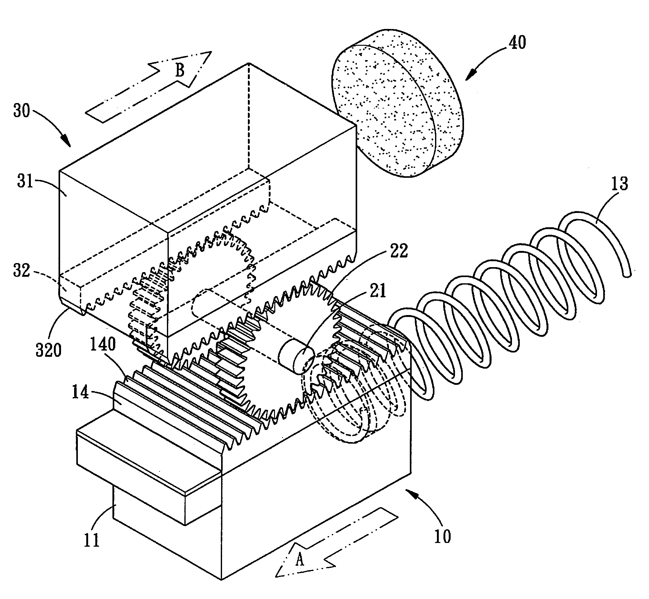
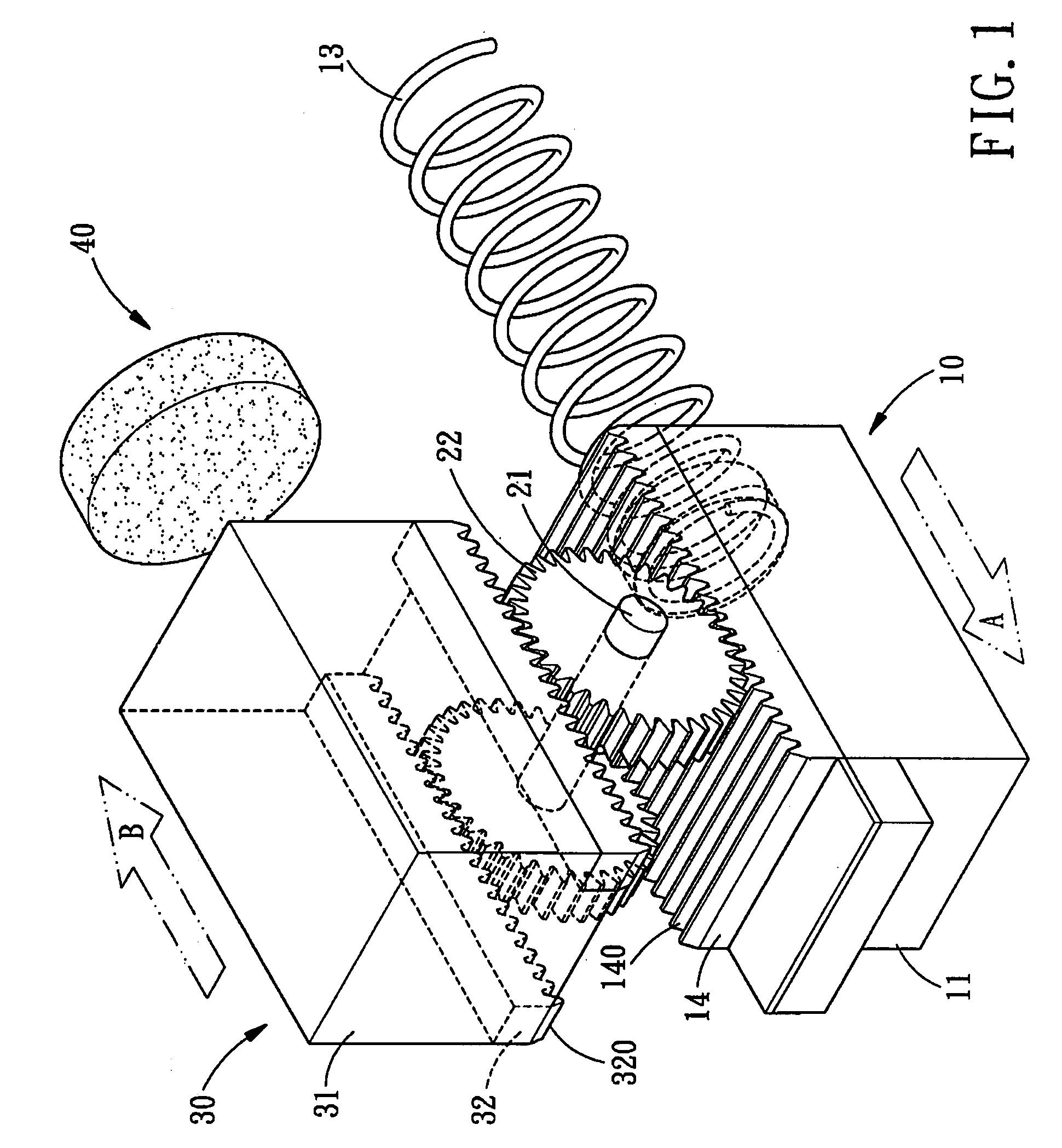
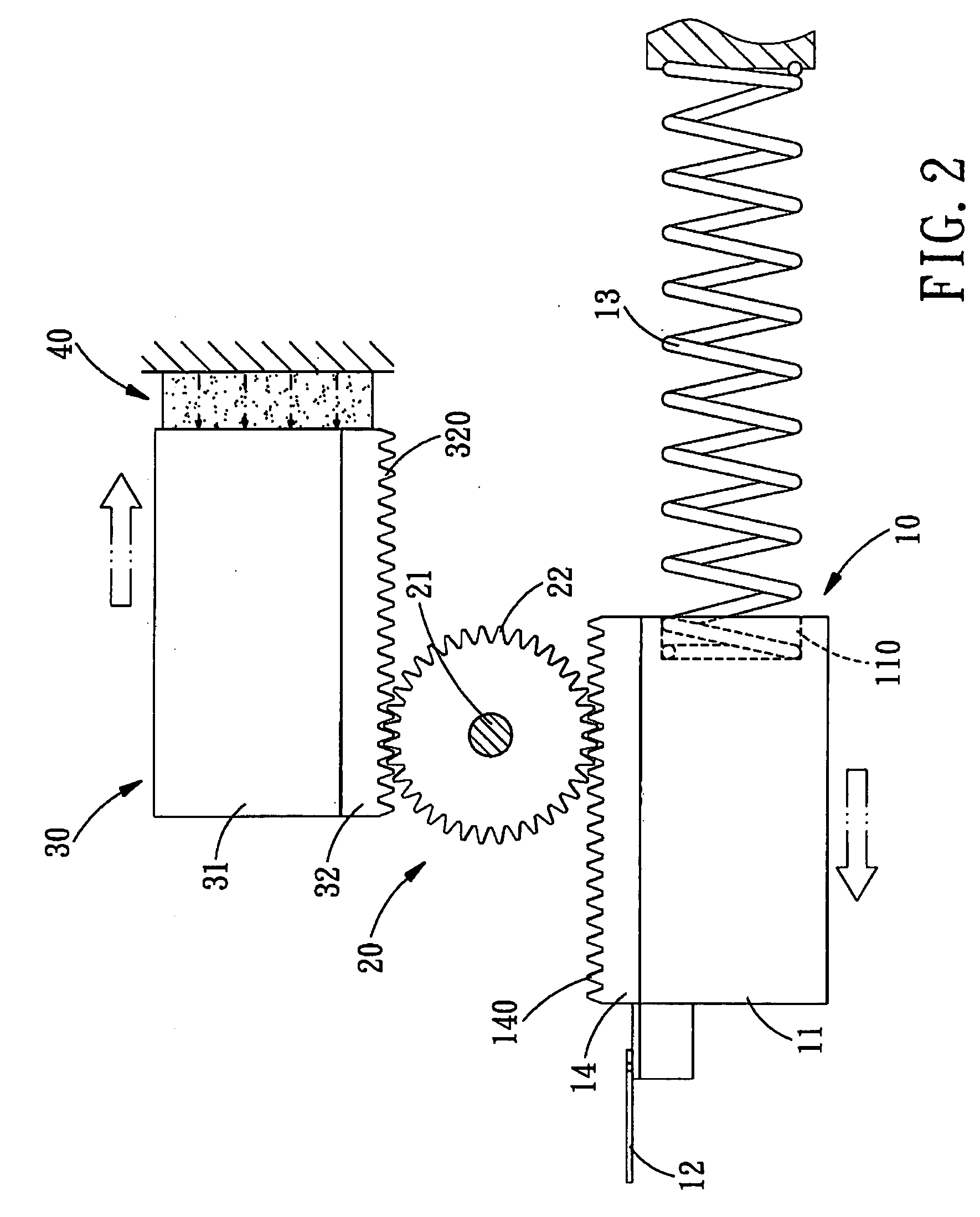
[0020]Referring to FIGS. 2 and 3, a counterforce-counteracting device for a nailer in accordance with the present invention is shown, in normal condition, the active device 10 is located opposite to the weight device 30, and they are arranged one before the other as shown in FIG. 3. Referring to FIG. 2, when the active device 10 performs a striking motion, the active member 11 of the active device 10 moves towards one end thereof, and the nail-hitting member 12 strikes the nail into the object to be nailed. The first driving portion 140 of the first driving member 14 of the active member 11 drives the engaging portion 22 of the rotating member 20 to move, and then the engaging portion 22 of the rotating member 20 moves the second driving portion 320 of the second driving member 32 of the weight member 31, so as to produce a counterforce through the engagement rotation and to achieve the buffering effect. In addition, when the active member 11 returns to the normal condition after ha...
second embodiment
[0021]Referring to FIG. 4 again, a counterforce-counteracting device for a nailer in accordance with the present invention is shown, one end of the first driving member 14 of the active member 11 of the active device 10 is defined with a penetrated first positioning portion 141, and one end of the second driving portion 32 of the weight member 31 of the weight device 30 is defined with a penetrated second positioning portion 321 diagonally opposite the first positioning portion 141. The first positioning portion 141 of the first driving member 14 of the active member 11 and the second positioning portion 321 of the weight member 31 are provided for fixing a line-shaped pulling member 23, and the pulling member 23 winds around a containing portion 24 formed in the rotating member 20. The active device 10 cooperates with the weight device 30 to drive the pulling member 23 to move, enabling the pulling member 23 to extend and retract, such that the active device 10 and the weight devic...
third embodiment
[0022]Referring to FIG. 5, a counterforce-counteracting device for a nailer in accordance with the present invention is shown, one end of the weight member 31 of the weight device 30 is formed with a containing portion 310 for receiving one end of a second elastic member 33, and the other end of the second elastic member 33 is abutted against the inside of the nailer. When the active device 10 performs a striking motion, the active member 11 of the active device 10 moves towards one end thereof, and the nail-hitting member 12 strikes the nail into the object to be nailed. The first driving portion 140 of the first driving member 14 of the active member 11 drives the engaging portion 22 of the rotating member 20 to move, and then the rotating portion 22 of the rotating member 20 moves the second driving portion 320 of the second driving member 32. In addition, after the second elastic member 33 received in the containing portion 310 of the weight member 31 produces a push force after...
PUM
| Property | Measurement | Unit |
|---|---|---|
| Time | aaaaa | aaaaa |
| Time | aaaaa | aaaaa |
| Weight | aaaaa | aaaaa |
Abstract
Description
Claims
Application Information