
Fluid ejection apparatus

a technology of ejection apparatus and nozzle, which is applied in the direction of printing, other printing apparatus, etc., can solve the problem that the nozzle may not be properly ejected, and achieve the effect of avoiding the ejection of the nozzl

Active Publication Date: 2009-03-26
BROTHER KOGYO KK
View PDF5 Cites 5 Cited by
  • Summary
  • Abstract
  • Description
  • Claims
  • Application Information

AI Technical Summary

Benefits of technology

[0009]Therefore, a need has arisen for fluid ejection apparatus which overcome these and other shortcomings of the related art. A technical advantage of the present invention is that when air is discharged from the fluid supply passage via the nozzles, the amount of ink also discharged via the nozzles is reduced.
[0010]According to an embodiment of the present invention, a fluid ejection apparatus comprises a fluid ejection head comprising a nozzle through which fluid is ejected, a fluid supply passage through which fluid is supplied to the fluid ejection head, a suction device configured to draw fluid from the nozzle, and a movable member positioned within a predetermined portion of the fluid supply passage. The movable member has at least one opening formed therethrough, and is configured to hold at least one air bubble therein. The movable member is further configured to move between a first position and a second position downstream of the first position in a fluid flowing direction. When the movable member is in the second position, the movable member partitions the predetermined portion of the fluid supply passage into a first space upstream of the movable member and a second space downstream of the movable member. Moreover, when the suction device transitions from an inactive state to an active state to draw ink from the nozzle, the movable member moves from the first position to the second position and remains in the second position until the suction device transitions from the active state to the inactive state.

Problems solved by technology

If air in the fluid supply passage flows into the inkjet head together with ink, ink may not be properly ejected from the nozzles.
Consequently, in the known inkjet recording apparatus, a significant amount of ink is discharged via the nozzles when air is discharged via the nozzles.

Method used


Image

  • Fluid ejection apparatus
  • Fluid ejection apparatus
  • Fluid ejection apparatus

Examples


Embodiment Construction

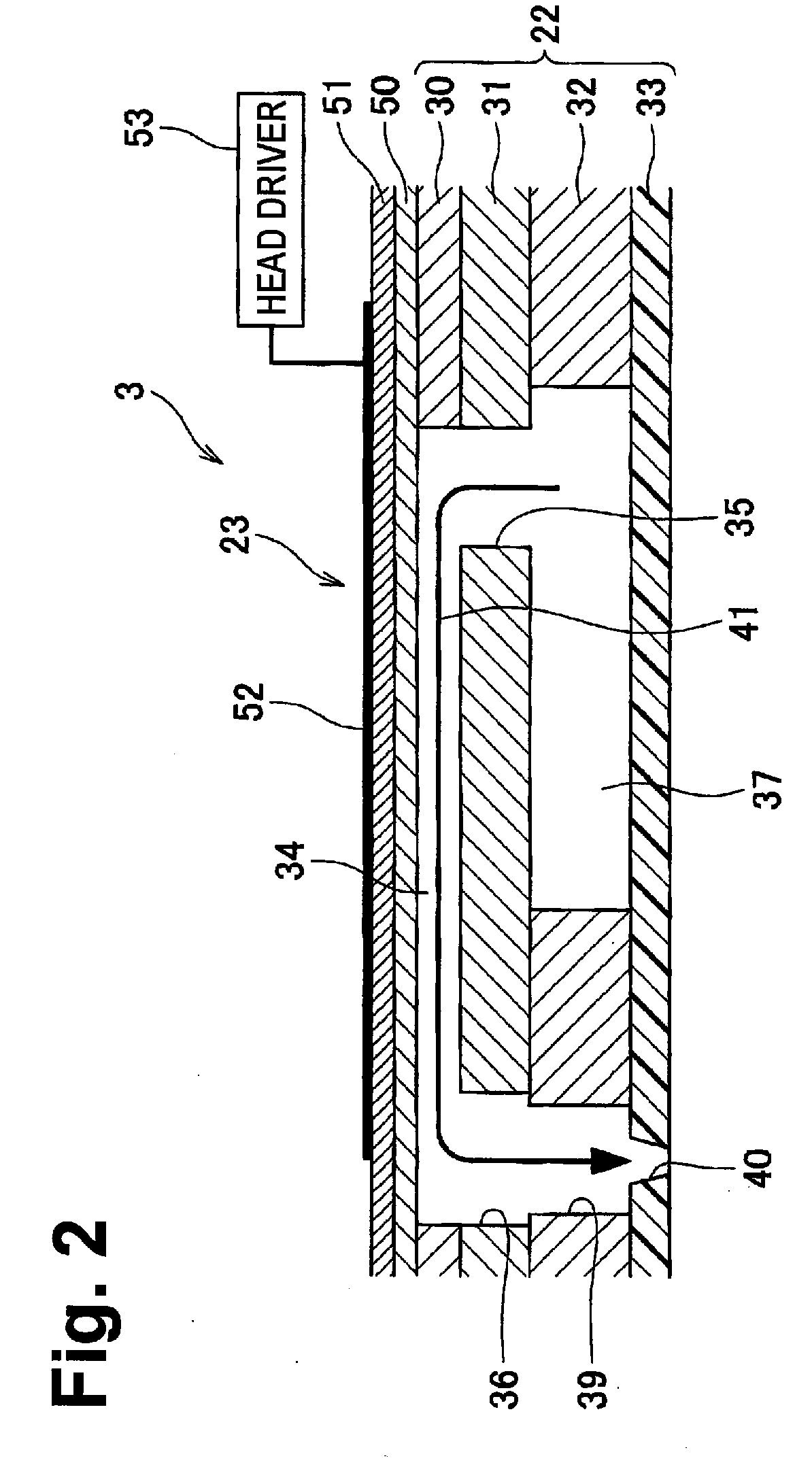
[0019]Embodiments of the present invention and their features and technical advantages may be understood by referring to FIGS. 1-6C, like numerals being used for like corresponding portions in the various drawings.

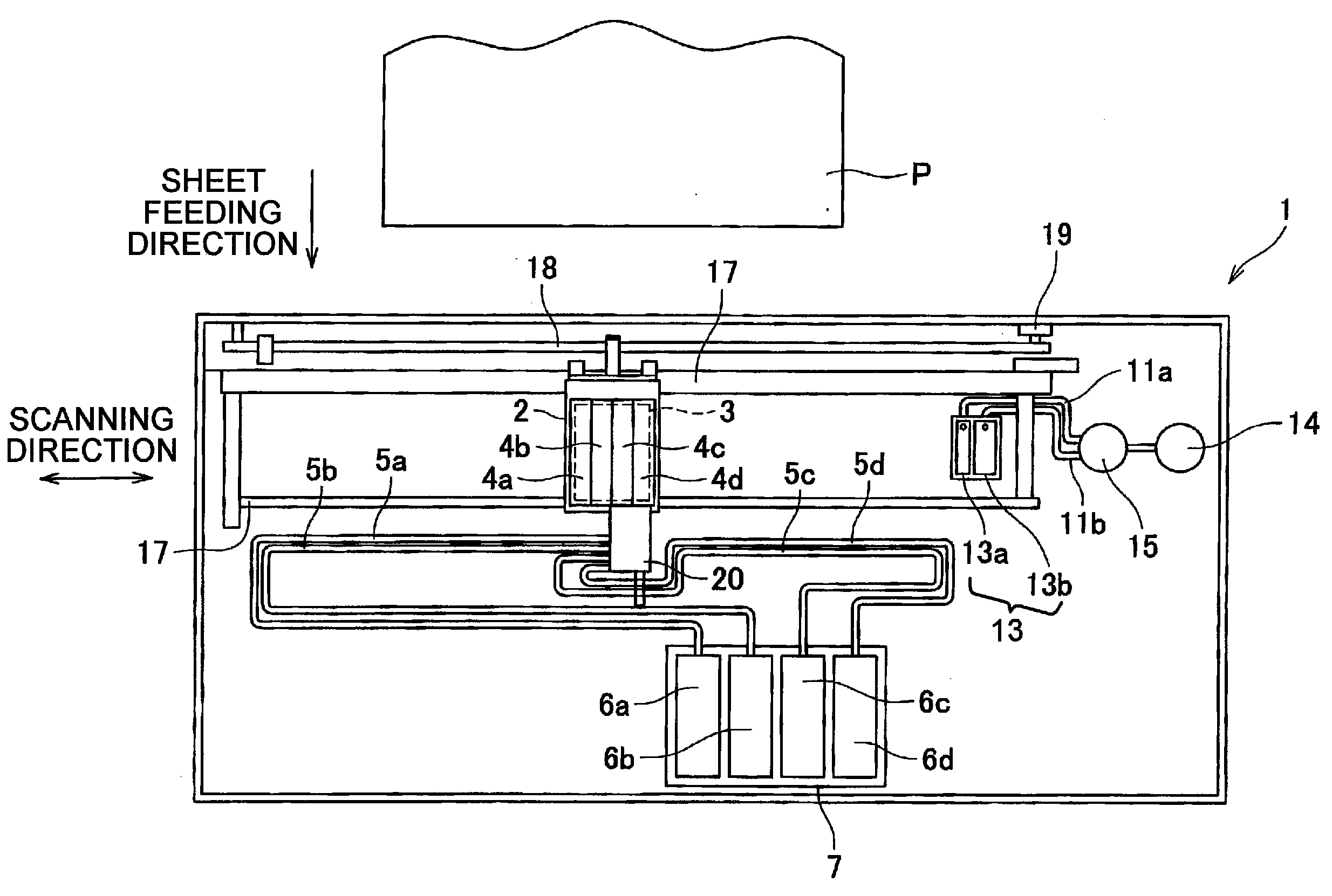
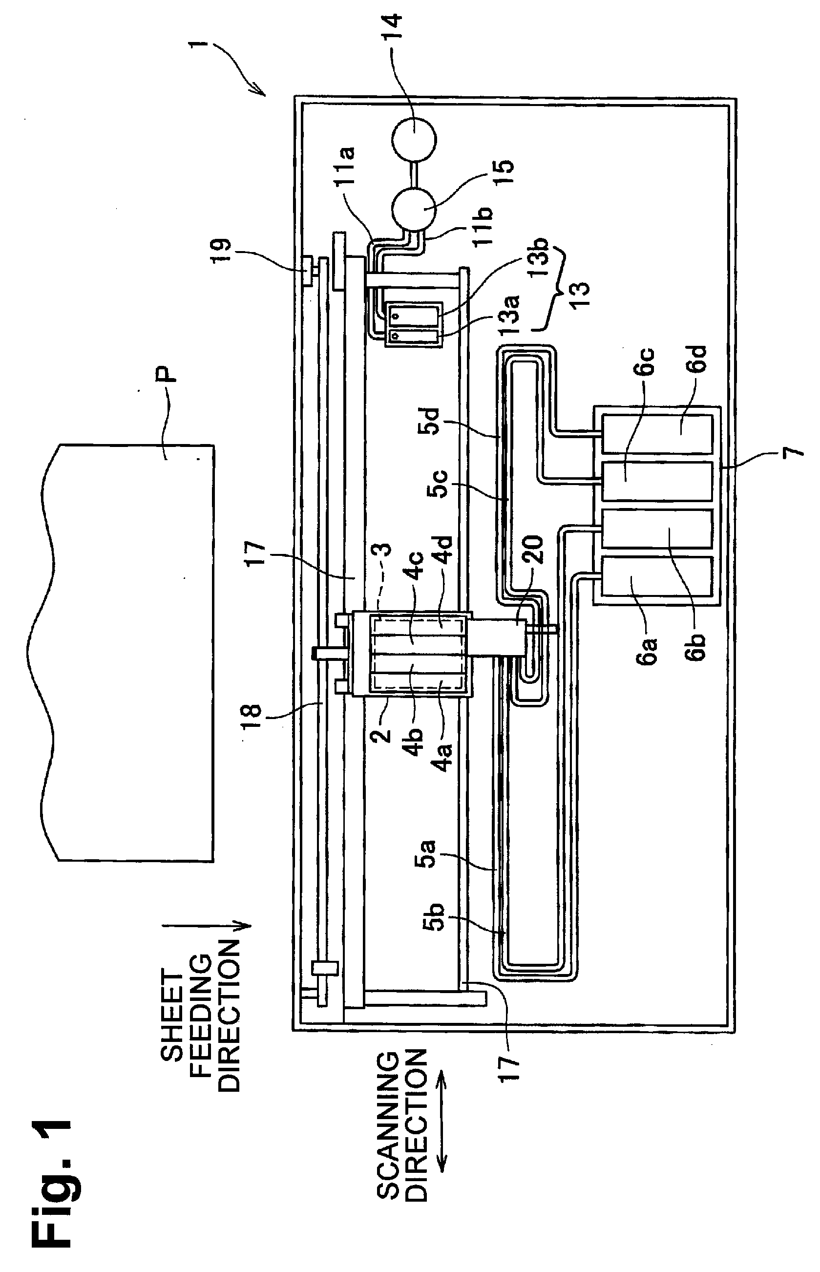
[0020]Referring to FIG. 1, a fluid ejection device, e.g., a printer 1, according to an embodiment of the present invention, may form, e.g., print, a desired image, e.g., text, on recording mediums, e.g., recording sheets P, by ejecting droplets of fluid, e.g., ink, from a fluid ejection head, e.g., inkjet head 3, toward the recording sheets P.

[0021]Printer 1 may comprise a carriage 2, inkjet head 3, sub-tanks 4a-4d, which herein after collectively are referred to as sub-tank 4, ink cartridges 6a-6d, which herein after collectively are referred to as ink cartridge 6, a suction cap 13, and a suction device, e.g., a suction pump 14. Carriage 2 may be configured to reciprocate along one direction. Inkjet head 3 and sub-tank 4 may be mounted to carriage 2. Ink cartridge 6 may s...


PUM


Abstract

A fluid ejection apparatus includes a fluid ejection head comprising a nozzle through which fluid is ejected, a fluid supply passage through which fluid is supplied to the fluid ejection head, a suction device configured to draw fluid from the nozzle, and a movable member positioned within a predetermined portion of the fluid supply passage. The movable member has openings formed therethrough, and is configured to hold air bubbles therein. The movable member is further configured to move between a first position and a second position downstream of the first position in a fluid flowing direction. When the movable member is in the second position, the movable member partitions the predetermined portion of the fluid supply passage into a first space upstream of the movable member and a second space downstream of the movable member. Moreover, when the suction device transitions from an inactive state to an active state to draw fluid from the nozzle, the movable member moves from the first position to the second position and remains in the second position until the suction device transitions from the active state to the inactive state.

Description

CROSS REFERENCE TO RELATED APPLICATION[0001]The present application claims priority from Japanese Patent Application No. 2007-248323, filed on Sep. 26, 2007, the disclosure of which is incorporated herein by reference in its entirety.BACKGROUND OF THE INVENTION[0002]1. Field of the Invention[0003]The present invention relates generally to fluid ejection apparatus configured to eject droplets of fluid.[0004]2. Description of Related Art[0005]Known fluid recording apparatus, such as inkjet recording apparatus, eject ink droplets from nozzles to recording mediums, such as recording sheets, to form images, such as text images, on the recording mediums. An inkjet recording apparatus includes a fluid ejection head, e.g., an inkjet head, having nozzles, and an ink cartridge which stores ink therein and is connected to the inkjet head. When ink is consumed as ink droplets are ejected from the nozzles of the inkjet head, ink is supplied from the ink cartridge to the inkjet head.[0006]Air may...

Claims


Application Information

Patent Timeline
Patent Type & Authority Applications(United States)
IPC IPC(8): B41J2/14B41J2/00B41J2/17
CPCB41J2/16532B41J2/17513B41J29/38B41J2/17596B41J2/17553
Inventor UMEDA, TAKAICHIRO
Owner BROTHER KOGYO KK
Learn More