Coupling mechanism for material supply module

a technology of material supply module and coupling mechanism, which is applied in the direction of instruments, electrographic process equipment, optics, etc., can solve the problems of complex and expensive fabrication

Inactive Publication Date: 2009-03-26
XEROX CORP
View PDF4 Cites 29 Cited by
  • Summary
  • Abstract
  • Description
  • Claims
  • Application Information

AI Technical Summary

Benefits of technology

[0007]According to another aspect, there is provided a photoreceptor drum for use in producing an image in conjunction with a reprographic device. At one of its ends, the photoreceptor drum is joined with a cylinder flange having a concentric shaft that extends axially outwardly therefrom. A cylindrical coupling member extends axially outwardly from the concentric shaft and is con

Problems solved by technology

Because twisted triangular coupling member 40 of cylinder flange 34 generally twists in one direction an

Method used


Image

  • Coupling mechanism for material supply module
  • Coupling mechanism for material supply module
  • Coupling mechanism for material supply module

Examples


Embodiment Construction

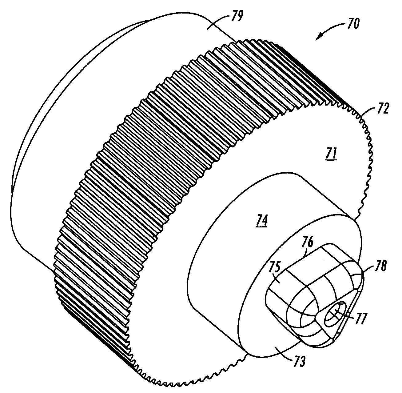
[0016]In accordance with an embodiment of the present invention, FIG. 4 shows a driven coupling 70 which may be attached to a photoreceptor drum at the photoreceptor attachment end 79 thereof. The driven coupling 70 includes a geared outside edge 72 and a cylinder flange 71 that has a concentric shaft 74 extending axially outwardly therefrom. Concentric shaft 74, in turn, has an outer surface 73, to which a driven coupling member 75 is centrally attached.

[0017]The driven coupling member 75 has a first, or bottom, end 76 that is attached to the outer surface 73 of the concentric shaft 74. Opposite first end 76, the driven coupling member 75 has a second, or top, end 78. As shown in FIGS. 4 and 5, in one embodiment of the present invention, the driven coupling member 75 may be tapered, or beveled, at its top end 78. In alternative embodiments, the driven coupling member 75 may be tapered along a larger portion of its length (i.e., along the distance between its respective ends 76, 78)...


PUM


Abstract

A coupling mechanism includes a driven coupling for mating with a driving coupling. The driven coupling includes a cylinder flange, a concentric shaft that extends axially outwardly from the flange, and a cylindrical driven coupling member that extends axially outwardly from the concentric shaft. The driven coupling member comprises a flexible membrane that encases non-rigid fill material, such as, e.g., a flowable granular material or a non-Newtonian fluid. The driven coupling member has a non-twisted, triangular cross-section, and is configured such that, when it is operationally engaged with the driving coupling, the non-rigid material substantially solidifies, thereby providing a substantially non-flexible structure for the membrane. The driven coupling may be connected to, for example, a photoreceptor drum of a material supply module, and the driving coupling may be connected to a reprographic device.

Description

BACKGROUND[0001]Many reprographic and / or electrostatographic image-forming devices, such as copiers, facsimile apparatus, printers, and the like include a replaceable or refillable material supply module. The material supply module is typically connected to such a device via a drive shaft and gear shaft coupling arrangement, which generally includes a drive shaft integral to the module that interacts with a gear shaft integral to the particular device.[0002]FIG. 1 shows a drive shaft and gear shaft coupling arrangement 20, which is currently used in the material supply module of copiers, facsimile apparatus, printers, and similar electrostatographic image forming devices. A drive gear 22 drives a driveshaft cylinder 24 of a drive shaft 25. Drive gear 22 includes a gear shaft 26 at its center and a geared outside edge 28. Gear shaft 26 has a front surface 30, which includes a twisted triangular coupling hole 32 having defined vertices 33 formed therein. Driveshaft cylinder 24 is fixe...

Claims


Application Information

Patent Timeline
IPC IPC(8): G03G15/00
CPCG03G21/186G03G15/757
Inventor PARISI, MICHAEL A.SEYFRIED, RICHARD W.SHAW, JOHN G.
Owner XEROX CORP
Why Eureka
Try Eureka