Horizontal field MRI shoulder coil

a shoulder coil and horizontal field technology, applied in the field of horizontal field mri shoulder coil, can solve the problem that existing quadrature coil designs do not provide optimal snr

Inactive Publication Date: 2009-03-26
HITACHI MEDICAL SYSTEMS AMERICA INC
View PDF11 Cites 16 Cited by
  • Summary
  • Abstract
  • Description
  • Claims
  • Application Information

AI Technical Summary

Benefits of technology

[0012]These and other objects of the present invention will become more readily apparent from a reading of the following detailed description taken in

Problems solved by technology

The existing quadrature coil designs do not provide optimal SNR due to the required separation of the anterior and posterior elements necessary to avoi

Method used


Image

  • Horizontal field MRI shoulder coil
  • Horizontal field MRI shoulder coil
  • Horizontal field MRI shoulder coil

Examples


Embodiment Construction

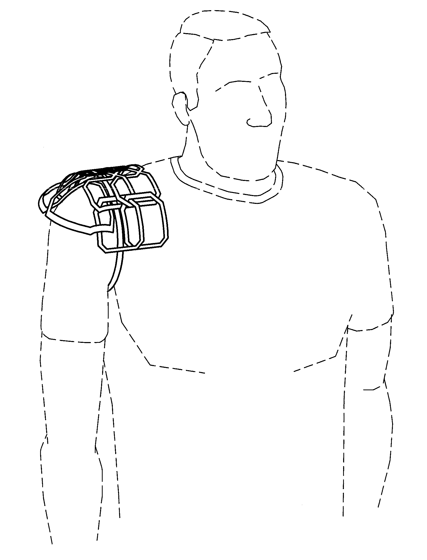
[0019]Referring now to the drawings wherein the showings are for purposes of illustrating numerous embodiments of the invention only and not for purposes of limiting the same, the figures illustrate the novel idea of a design of a radiofrequency (RF) receive coil (also commonly referred to as an imaging coil) for magnetic resonance imaging (MRI) in a horizontal field MRI system of a patient's shoulder region. When referring to the shoulder region, the patient's shoulder region will include three main areas: the superior section (the top of the patient's shoulder), the anterior section (the front of the patient's shoulder) and the posterior section (the back of the patient's shoulder).

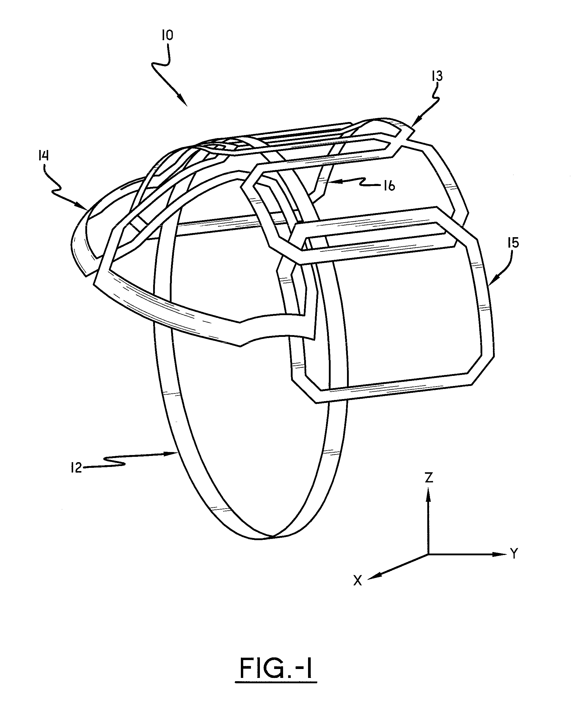
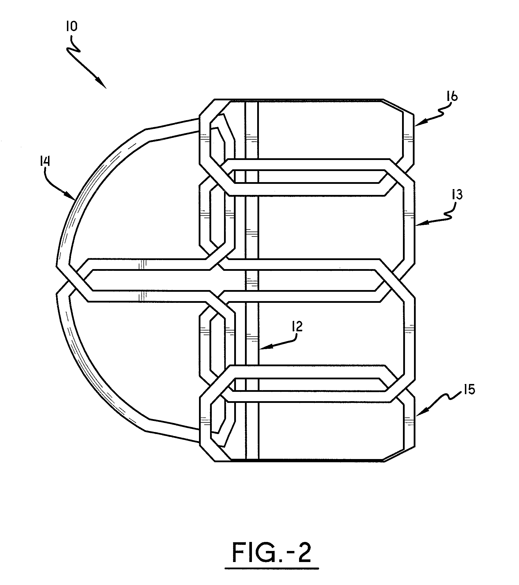
[0020]Referring to FIG. 1 and FIG. 2, a preferred embodiment of coil 10 has a five element design. Solenoid element 12 is positioned to wrap around the patient's shoulder, encompassing the superior, anterior and posterior sections of the patient's shoulder. Saddle element 13 and saddle element 14 are po...


PUM


Abstract

The present invention relates to a design of a radiofrequency (RF) receive coil (also commonly referred to as an imaging coil) for magnetic resonance imaging (MRI) in a horizontal field MRI system of a patient's shoulder region.

Description

TECHNICAL FIELD[0001]The invention relates generally to a design of a radiofrequency receive coil designed for magnetic resonance imaging of a patient's anatomy. More specifically, the invention relates to a design of a radiofrequency receive coil for magnetic resonance imaging in a horizontal field magnetic resonance imaging system of a patient's shoulder region.BACKGROUND OF THE INVENTION[0002]Magnetic resonance imaging (MRI) is a medical diagnostic imaging technique used to diagnose many types of injuries and medical conditions. An MRI system includes a main magnet for generating a main magnetic field through an examination region. The main magnet is arranged such that its geometry defines the examination region. The orientation of the main magnet defines whether the MRI system is classified as a horizontal field system or a vertical field system. In a horizontal field system, the static main magnetic field is typically oriented in the head-foot (H-F) direction relative to the pr...

Claims


Application Information

Patent Timeline
IPC IPC(8): A61B5/055
CPCG01R33/365G01R33/3415
Inventor GUAN, YIPINGARCHIBALD, KEVIN A.KOLECKI, JOSEPH M.
Owner HITACHI MEDICAL SYSTEMS AMERICA INC
Why Eureka
Try Eureka