Ocular Implant Architectures

a technology of ocular implants and implants, applied in the field of devices, can solve the problems of damage to the optic nerve that transmits sensory information, loss of peripheral vision,

Inactive Publication Date: 2009-03-26
ALCON INC
View PDF29 Cites 107 Cited by
  • Summary
  • Abstract
  • Description
  • Claims
  • Application Information

AI Technical Summary

Problems solved by technology

Researchers have theorized prolonged exposure to high intraocular pressure causes damage to the optic nerve that transmits sensory information from the eye to the brain.
This damage to the optic nerve results in loss of peripheral vision.
As glaucoma progresses, more and more of the visual field is lost until the patient is completely blind.

Method used


Image

  • Ocular Implant Architectures
  • Ocular Implant Architectures
  • Ocular Implant Architectures

Examples


Embodiment Construction

[0033]The following detailed description should be read with reference to the drawings, in which like elements in different drawings are numbered identically. The drawings, which are not necessarily to scale, depict exemplary embodiments and are not intended to limit the scope of the invention. Examples of constructions, materials, dimensions, and manufacturing processes are provided for selected elements. All other elements employ that which is known to those of skill in the field of the invention. Those skilled in the art will recognize that many of the examples provided have suitable alternatives that can be utilized.

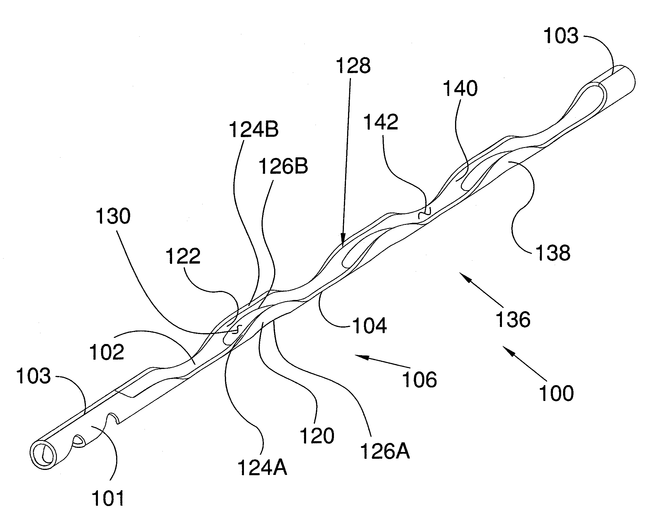
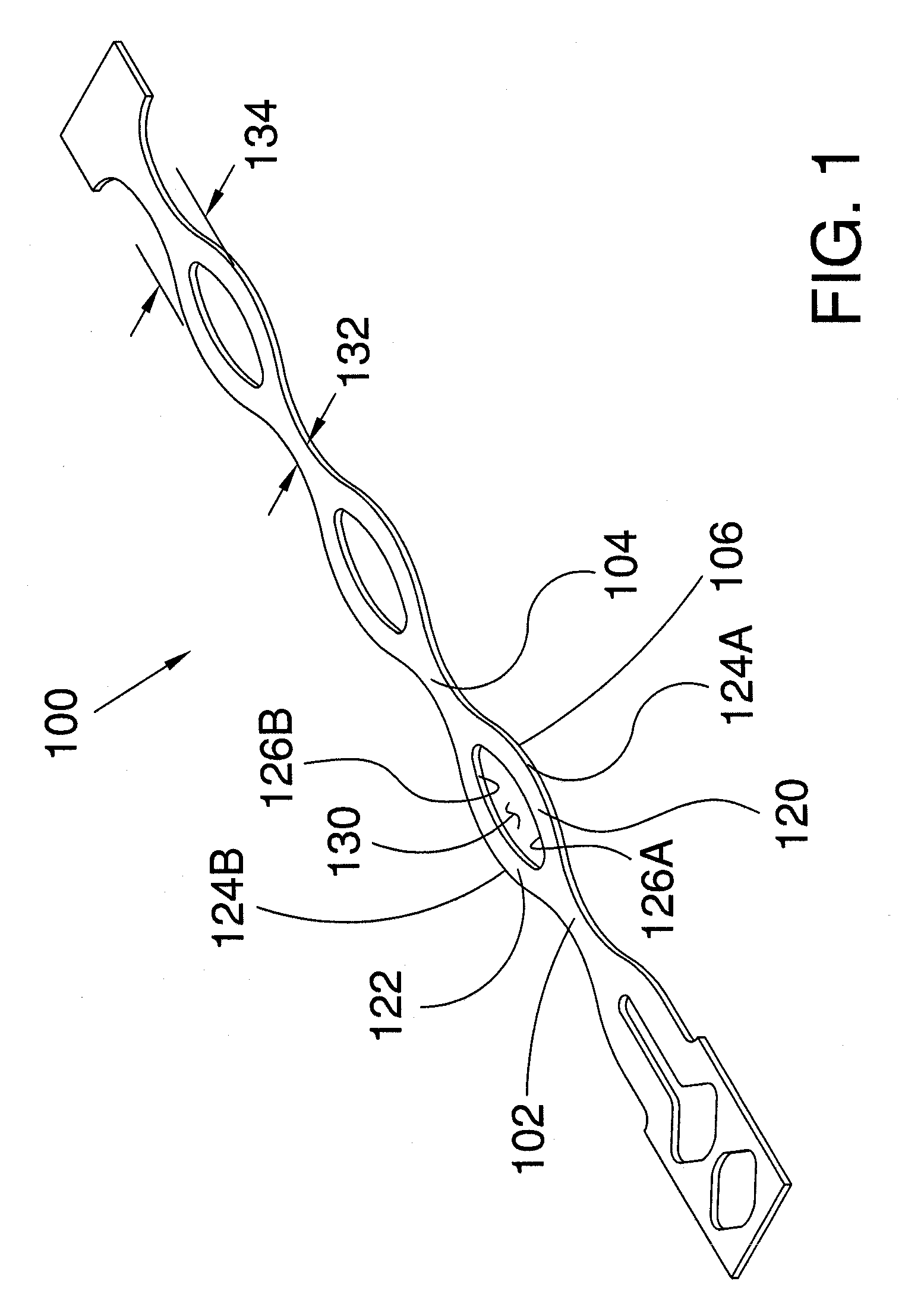
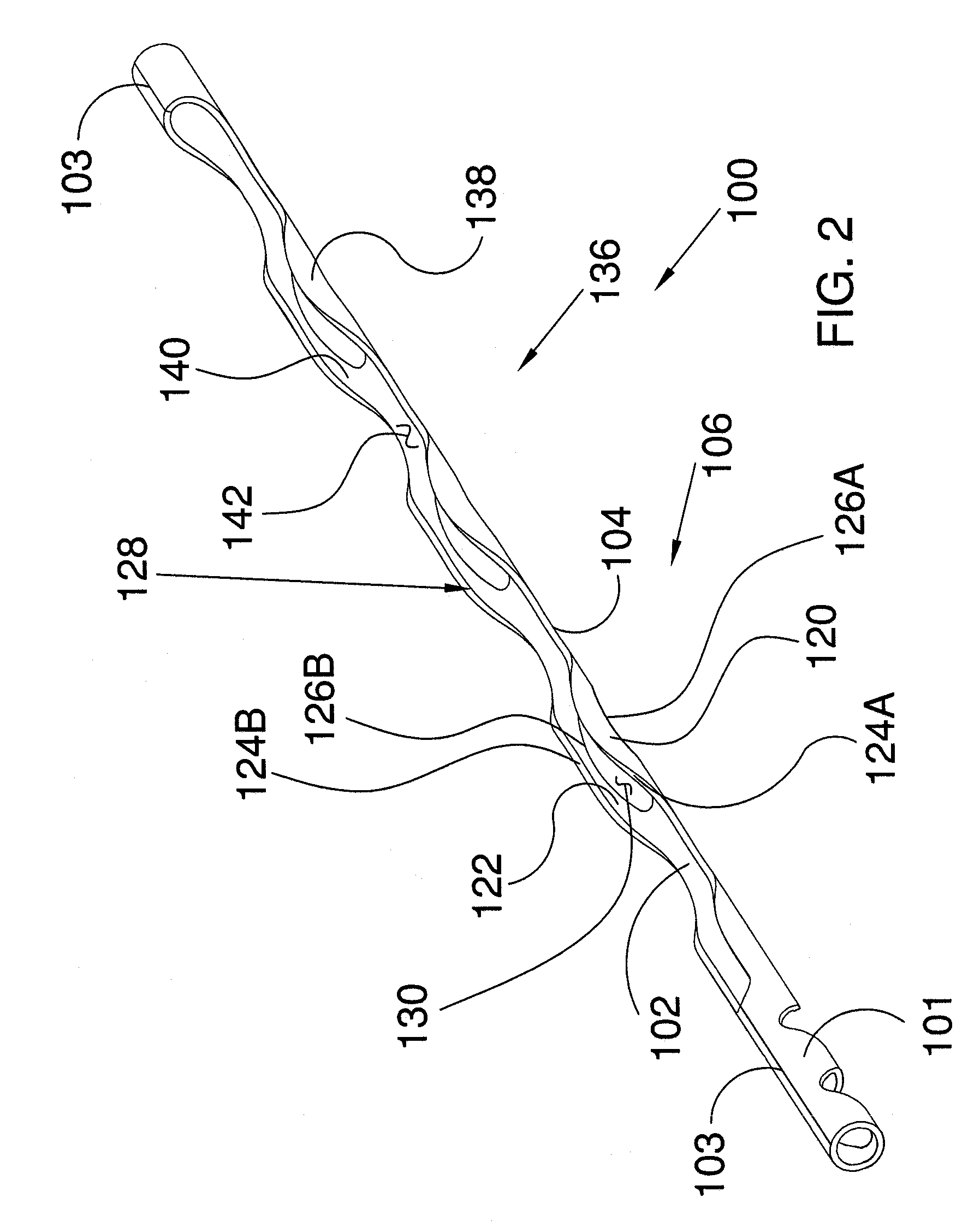
[0034]FIG. 1 is an isometric view showing a body 100 that may be used to form an ocular implant in accordance with one exemplary embodiment of the invention. Body 100 comprises a first spine 102, a second spine 104, and a first frame 106 disposed between first spine 102 and second spine 104. In the embodiment of FIG. 1, first frame 106 comprises a first strut 120 and...


PUM


Abstract

An ocular implant having a first spine; a second spine; a first strut extending in an axial direction Z between the first spine and the second spine; a second strut extending in an axial direction Z between the first spine and the second spine; wherein an angular dimension θ of a first edge of each strut undulates as the strut extends in the axial direction Z between the first spine and the second spine; and wherein a radius r of an outer surface of each strut remains substantially constant as the strut extends the axial direction Z between the first spine and the second spine.

Description

CROSS REFERENCE TO RELATED APPLICATIONS[0001]This application is a continuation-in-part of U.S. application Ser. No. 11 / 860,318, filed Sep. 24, 2007, and claims priority to U.S. Provisional Application No. 61 / 033,746, filed Mar. 4, 2008, the disclosures of which are incorporated by reference as if fully set forth herein.INCORPORATION BY REFERENCE[0002]All publications and patent applications mentioned in this specification are herein incorporated by reference to the same extent as if each individual publication or patent application was specifically and individually indicated to be incorporated by reference.FIELD OF THE INVENTION[0003]The present invention relates generally to devices that are implanted within the eye. More particularly, the present invention relates to devices that facilitate the transfer of fluid from within one area of the eye to another area of the eye.BACKGROUND OF THE INVENTION[0004]According to a draft report by The National Eye Institute (NEI) at The United ...

Claims


Application Information

Patent Timeline
Patent Type & Authority Applications(United States)
IPC IPC(8): A61F2/16
CPCA61F2/14A61F9/00781A61F2250/0067A61M5/00
Inventor SCHIEBER, ANDREW T.EUTENEUER, CHARLES L.
Owner ALCON INC
Why Eureka
Try Eureka