Common pipelayer frame for multiple machine configurations

a technology of pipelayers and frames, applied in mechanical equipment, special-purpose vessels, transportation and packaging, etc., can solve the problems of converting bulldozers to pipelayers, requiring a lot of time and effort by service technicians, and requiring many replacement parts

Inactive Publication Date: 2009-04-02
CATERPILLAR INC
View PDF16 Cites 9 Cited by
  • Summary
  • Abstract
  • Description
  • Claims
  • Application Information

AI Technical Summary

Problems solved by technology

Problems with converting bulldozers to pipelayers have arisen, particularly in relation to machines with varying configurations.
Problems occur in quickly and easily adjusting pipelayer frames to accommodate these various configurations.
Service technicians require much time and effort, as well as numerous replacement parts, to change a pipelayer from a narrow configuration to a wide configuration.
Although the system of the '888 publication may reduce the time and effort associated with converting between various pipelayer configurations, it may still be difficult and cumbersome to use.
Specifically, the system of the '888 publication requires precision to adequately fit the frame to a given width and thus, the conversion time and effort may still be excessive for an inexperienced technician.

Method used


Image

  • Common pipelayer frame for multiple machine configurations
  • Common pipelayer frame for multiple machine configurations
  • Common pipelayer frame for multiple machine configurations

Examples


Embodiment Construction

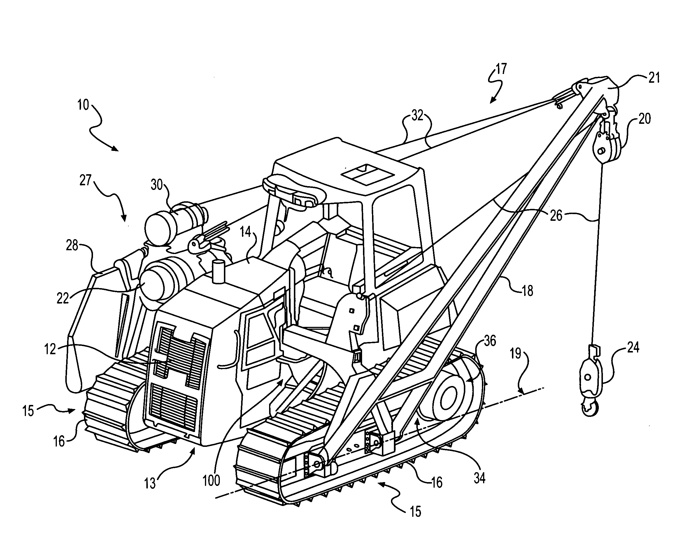
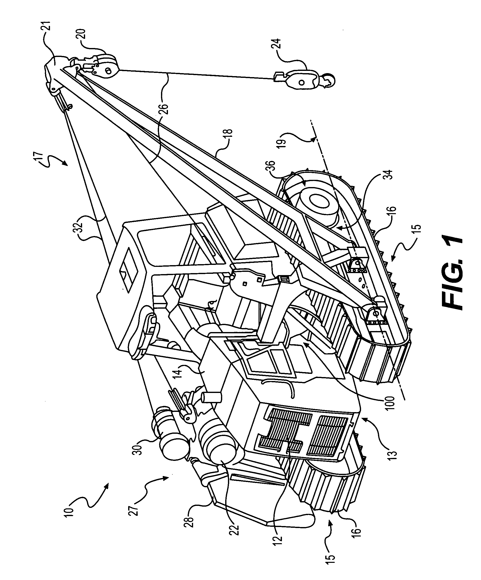
[0013]FIG. 1 illustrates an exemplary disclosed machine 10. Machine 10 may be a crawler-type tractor and may perform tasks associated with an industry such as construction. Machine 10 may include an engine 12 mounted within an engine hood or compartment 14 and located on a chassis 13. Machine 10 may also include a drive system (not shown) connected to engine 12 for transmitting power from engine 12 to one or more track assemblies 15 to propel machine 10.

[0014]In one embodiment, machine 10 may be configured as a pipelayer (shown in FIG. 1). As such, machine 10 may include a boom assembly 17 mounted to a pipelayer frame 100. Boom assembly 17 may be removably attached to pipelayer frame 100 and may include a boom 18 such as a lattice type boom. Boom assembly 17 may further include a pulley block 20 attached to a distal end 21 of boom 18, and a winch 22. A cable 26 may be attached to winch 22 and wound over pulley block 20. A hoist hook 24 may be suspended from cable 26. As such, a hois...


PUM


Abstract

A pipelayer frame for a track-type machine having an engine compartment, a first track frame, and a second track frame is disclosed. The frame has a center frame removably attachable within the engine compartment, a first side frame removably attachable to the first track frame and to the center frame, and a second side frame removably attachable to the second track frame and to the center frame. The frame also has a spacer assembly removably attachable to the first side frame. The frame further has an adjustable assembly located between the second side frame and the center frame, the adjustable assembly being configured to adjust a distance between the second side frame and the center frame.

Description

TECHNICAL FIELD[0001]This disclosure is directed to a pipelayer frame and, more particularly, to a common pipelayer frame that may be used for multiple machine configurations.BACKGROUND[0002]Pipelayers are track-type work machines used in pipelaying operations, in which the pipelayer raises, lowers, and carries heavy pipes. In order to reduce the cost of producing pipelayers, standard bulldozer tractors are often converted into pipelayers. This conversion is accomplished by the installation of a pipelayer frame onto the standard bulldozer. The pipelayer frame typically includes a boom frame attached to one side of the bulldozer chassis and a counterweight frame attached to an opposing side of the chassis. With the boom and counterweight frames attached, the bulldozer effectively becomes a pipelayer.[0003]Problems with converting bulldozers to pipelayers have arisen, particularly in relation to machines with varying configurations. That is, bulldozers can be configured with narrow co...

Claims


Application Information

Patent Timeline
Patent Type & Authority Applications(United States)
IPC IPC(8): B66C23/26B63B35/03
CPCB66C23/44
Inventor STYCK, WAYNE GEORGECAMACHO, TIMOTHY EDWARD
Owner CATERPILLAR INC
Why Eureka
Try Eureka