Small gamma shielded shorted patch RFID tag

Active Publication Date: 2009-04-16
ASSA ABLOY AB
View PDF17 Cites 153 Cited by
  • Summary
  • Abstract
  • Description
  • Claims
  • Application Information

AI Technical Summary

Benefits of technology

[0008]A small passive wireless transponder of the present invention has the unique ability to withstand medical gamma ray sterilization and function in the presence of an implanted (in the human body) metal device, or a non-implanted metal surgical tool, or a non-metallic implant or surgical tool for the purpose of remote (1-15 feet) electronic digital identification. The transponder is a small (less than 1 inch long, ½ in. wide, and ⅛ in. inch thick) medical grade plastic, silicon, or epoxy encapsulated tag that is capable of mounting onto an implanted metal orthopedic appliance, or metal shafted surgical tool. The electrically insulating substrate material is comprised of a high dielectric and low loss tangent material that facilitates the drastic miniaturization and

Problems solved by technology

These small “capsules” contain their own “onboard” antenna, which suffer extreme radio frequency degradation and detuning due to interference created by the proximity of the metals utilized in surgical tools, storage cases and implantable devices.
This “virtual” contact requirement makes communicat

Method used


Image

  • Small gamma shielded shorted patch RFID tag
  • Small gamma shielded shorted patch RFID tag
  • Small gamma shielded shorted patch RFID tag

Examples


Embodiment Construction

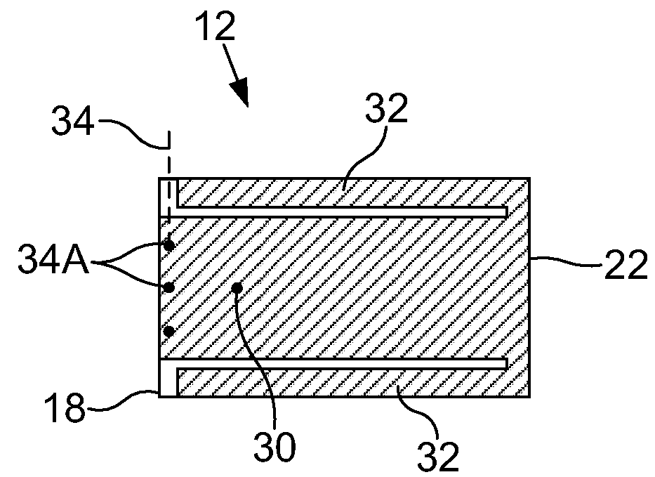
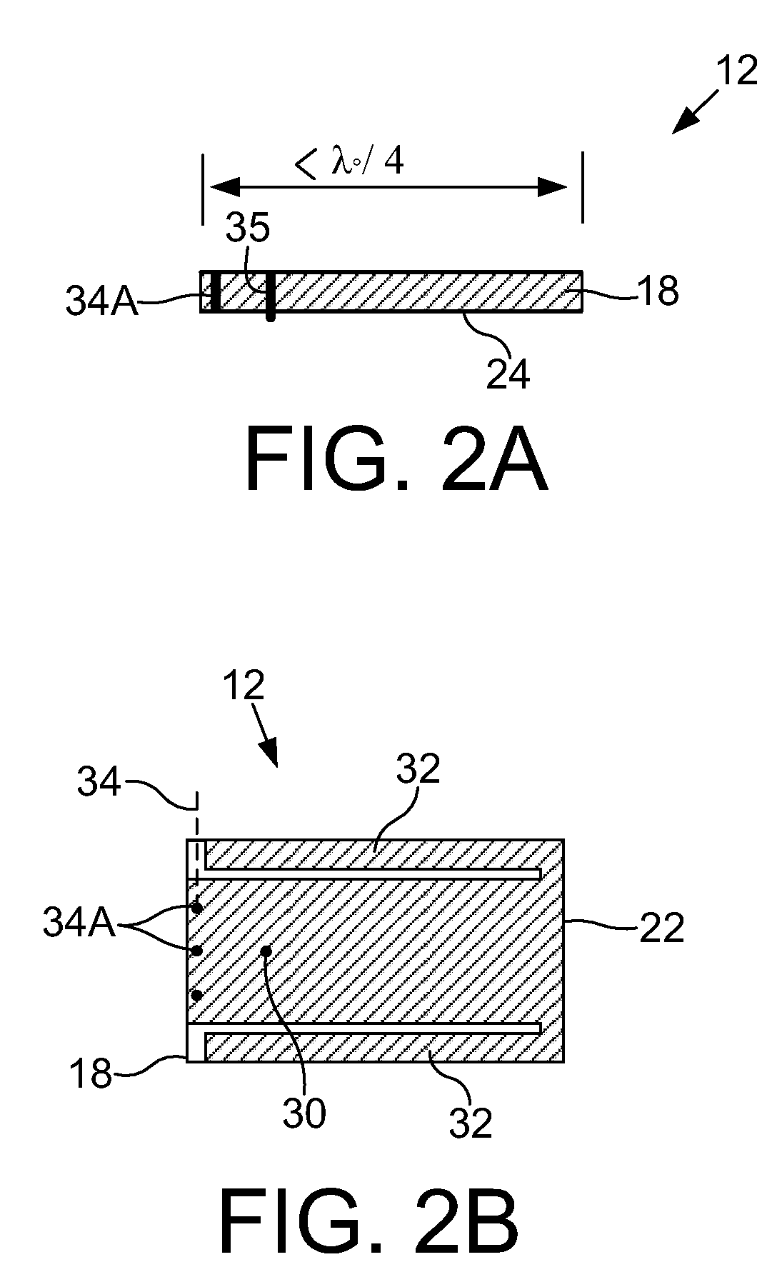
[0023]Referring now to the drawings, and more particularly to FIGS. 2-11, there is shown an embodiment of an RFID tag (transponder) 10 of the present invention, which generally includes a circuit board assembly 12, backplane 14 and overmolded housing 16.

[0024]Circuit board assembly 12 includes a circuit board 18, an RFID circuit 20, an antenna 22, and a metallic ground plane 24. Circuit board or substrate 18 has a first side 26 and a second side 28. Circuit board 18 carries antenna 22 on first side 26. Circuit board 18 carries RFID circuit 20 and ground plane 24 on second side 28.

[0025]Circuit board or substrate 18 may be constructed from a material with a high dielectric constant of greater than approximately 4. A substrate material that has a high dielectric constant such as a ceramic filled polytetraflouroethylene (PTFE) or metal oxide ceramic provides good strength, easy processing and a low thermal coefficient of expansion. The high dielectric material permits further miniaturi...


PUM


Abstract

An RFID tag includes a substrate made of a material with a high dielectric constant of greater than approximately 4 and having a first side and a second side. A patch antenna is mounted to the first side of the substrate. A metallic ground plane is mounted to the second side of the substrate, and includes a feed through hole. A metallic backplane is coupled with the ground plane, on a side of the ground plane opposite the substrate. The backplane and/or the ground plane includes a recess. An RFID circuit is positioned within the recess. A shorting wall includes a plurality of through holes extending through the substrate and interconnecting the antenna with the ground plane. The plurality of through holes are generally linearly arranged relative to each other along an edge of the ground plane. An electrically conductive via extends through the substrate and the feed through hole of the ground plane. The via has a diameter which is slightly less than the feed through hole. The via interconnects the antenna with the RFID circuit. The via is at a distance from the shorting wall whereby an impedance of the RFID circuit approximately matches an impedance of the antenna.

Description

CROSS REFERENCE TO RELATED APPLICATIONS[0001]This is a non-provisional application based upon U.S. provisional patent application Ser. Nos. 61 / 014,179, entitled “SMALL GAMMA SHIELDED SHORTED-PATCH RFID TAG”, filed Dec. 17, 2007; and 60 / 979,600, entitled “SMALL GAMMA SHIELDED SHORTED-PATCH RFID”, filed Oct. 12, 2007, which are incorporated herein by reference.BACKGROUND OF THE INVENTION[0002]1. Field of the Invention[0003]The present invention relates to RFID tags, and, more particularly, to RFID tags used for identification, inventory and tracking applications.[0004]2. Description of the Related Art[0005]Radio frequency identification (RFID) tags are well known throughout industry, and are being increasingly utilized for supply chain management, inventory management, and logistic control. These tags can be written to and read from a handheld transceiver or fixed portal. Small glass encapsulated low frequency tags are currently being utilized on surgical tools, storage cases and impl...

Claims


Application Information

Patent Timeline
IPC IPC(8): G08B13/14
CPCG06K19/07735G06K19/07786G06K19/07749
Inventor WESTRICK, MICHAEL D.
Owner ASSA ABLOY AB
Why Eureka
Try Eureka