

Control circuit and method for maintaining high efficiency in switching regulator
a switching regulator and control circuit technology, applied in the direction of dc-dc conversion, power conversion systems, instruments, etc., can solve the problems of high high complexity and cost of circuits, and the physical size of capacitors c11/b> must be huge to store large amounts of charge, etc., to achieve low switching and conduction losses, less switch requirements, and constant output voltage
- Summary
- Abstract
- Description
- Claims
- Application Information
AI Technical Summary
Benefits of technology
Problems solved by technology
Method used
Image

Examples
Embodiment Construction
[0031]Reference will now be made in detail to the present embodiments of the invention, examples of which are illustrated in the accompanying drawings. Wherever possible, the same reference numbers are used in the drawings and the description to refer to the same or like parts.
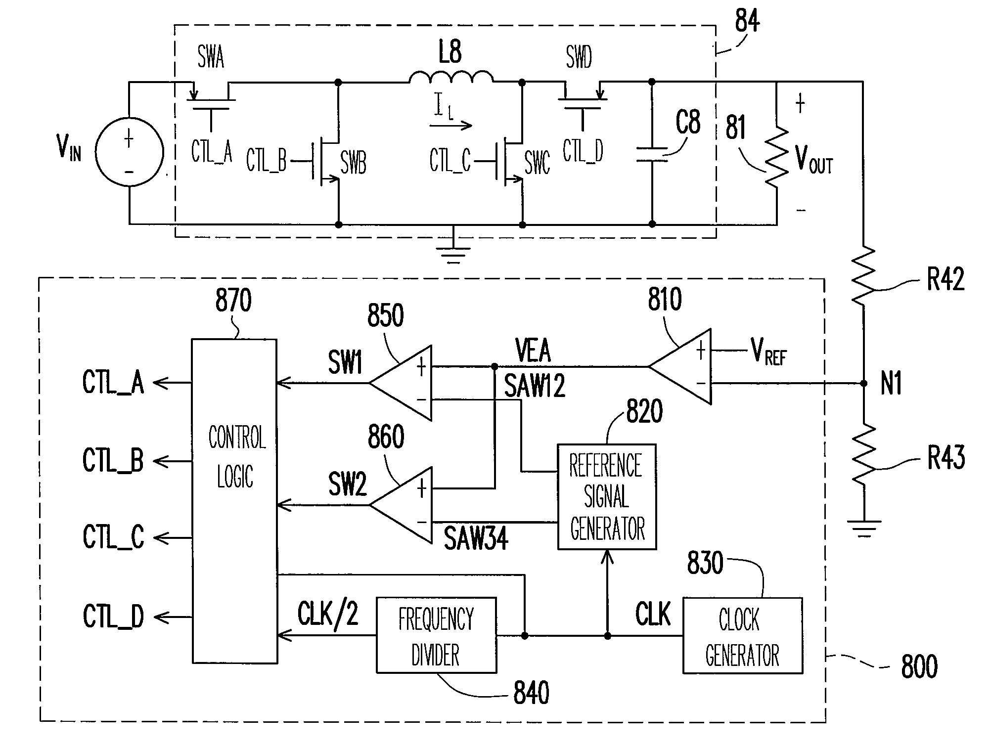
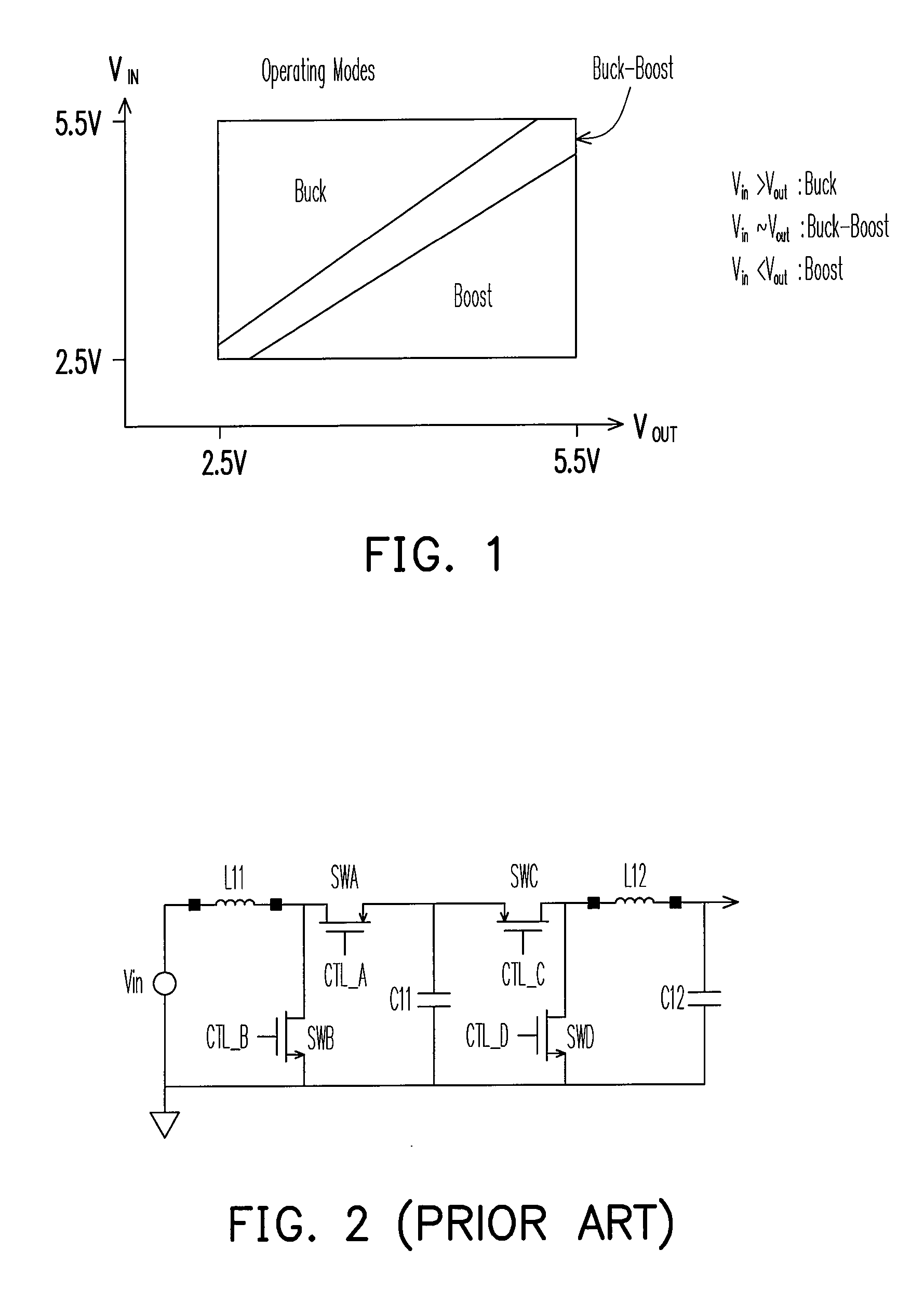
[0032]In an embodiment according to the invention, high efficiency control circuit and method for operating a switching regulator are provided. The switching regulator can regulate an output voltage higher, lower, or close to the input voltage. The switching regulator may be synchronous or non-synchronous. The control circuit can operate the switching regulator in buck mode (MODE 1), boost mode (MODE 4), or buck-boost mode (MODE 2 OR MODE 3). In mode 1, the switching regulator regulates an output voltage that is less than the input voltage. In mode 4, the switching regulator regulates an output voltage that is greater than the input voltage. In mode 2 or mode 3, the switching regulator regulates the output vol...
PUM
 Abstract
Description
Claims
Application Information