Caster with brake unit and direction unit

a brake unit and caster technology, applied in the field of casters, can solve problems such as damage to objects, and achieve the effect of easy telling

Inactive Publication Date: 2009-05-07
CHU KEIO
View PDF15 Cites 34 Cited by
  • Summary
  • Abstract
  • Description
  • Claims
  • Application Information

AI Technical Summary

Benefits of technology

[0007]The primary object of the present invention is to provide a caster including a first lever to control the braking of the caster and a second lever to direction that the caster moves. The second lever is located in t

Problems solved by technology

Nevertheless, the casters will move when the object is locat

Method used


Image

  • Caster with brake unit and direction unit
  • Caster with brake unit and direction unit
  • Caster with brake unit and direction unit

Examples


Embodiment Construction

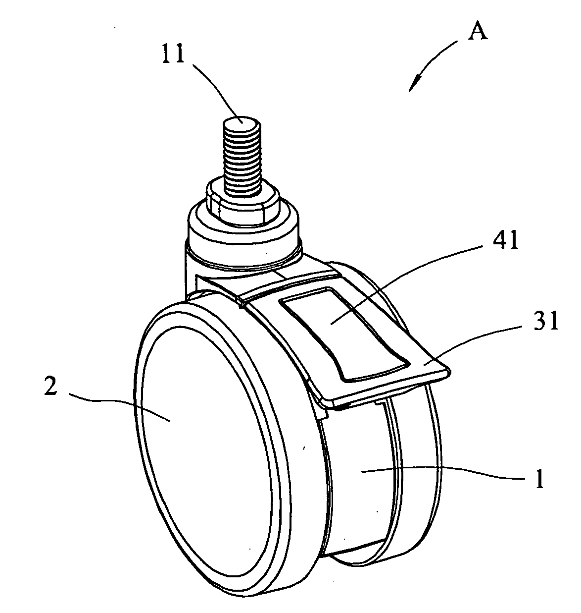
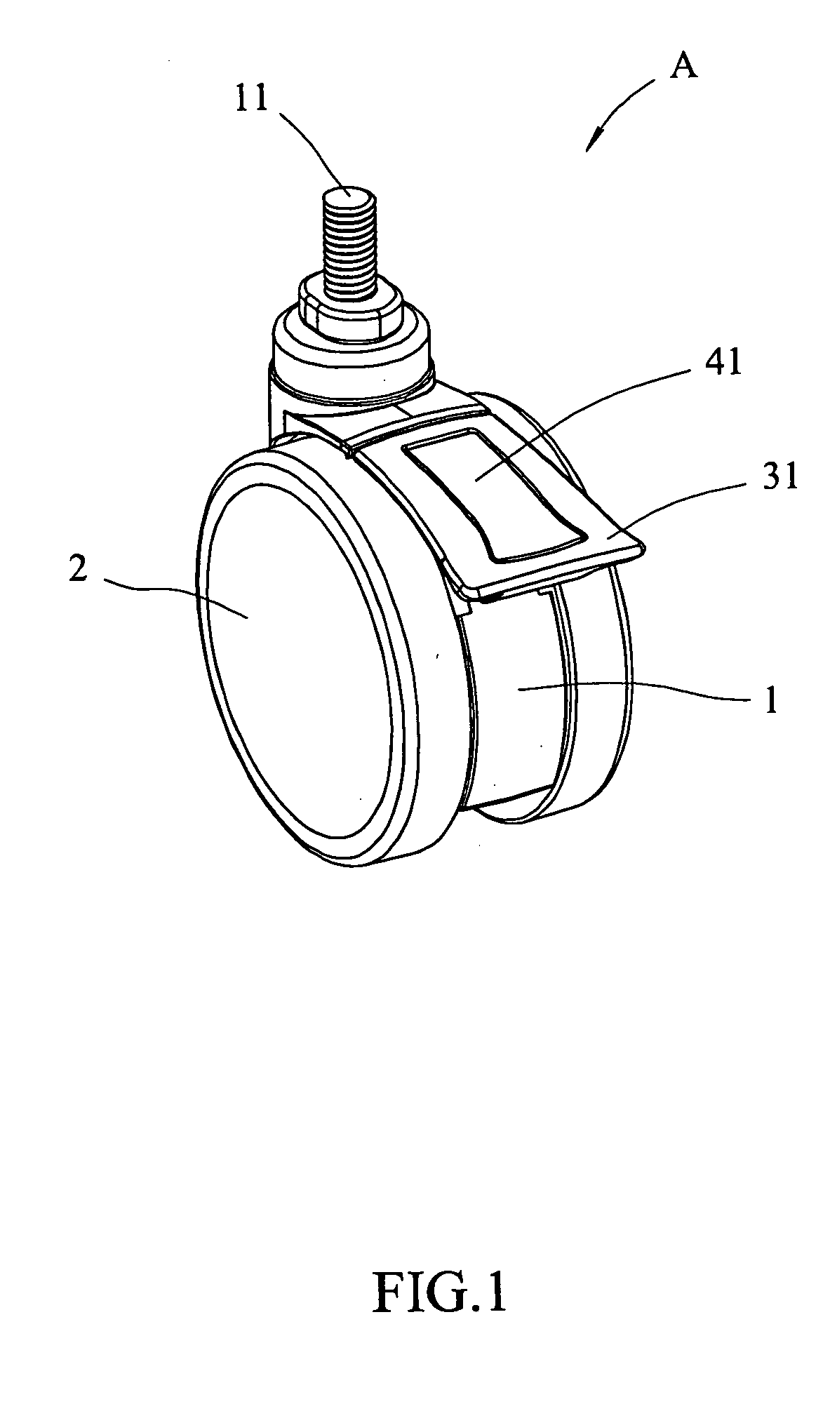
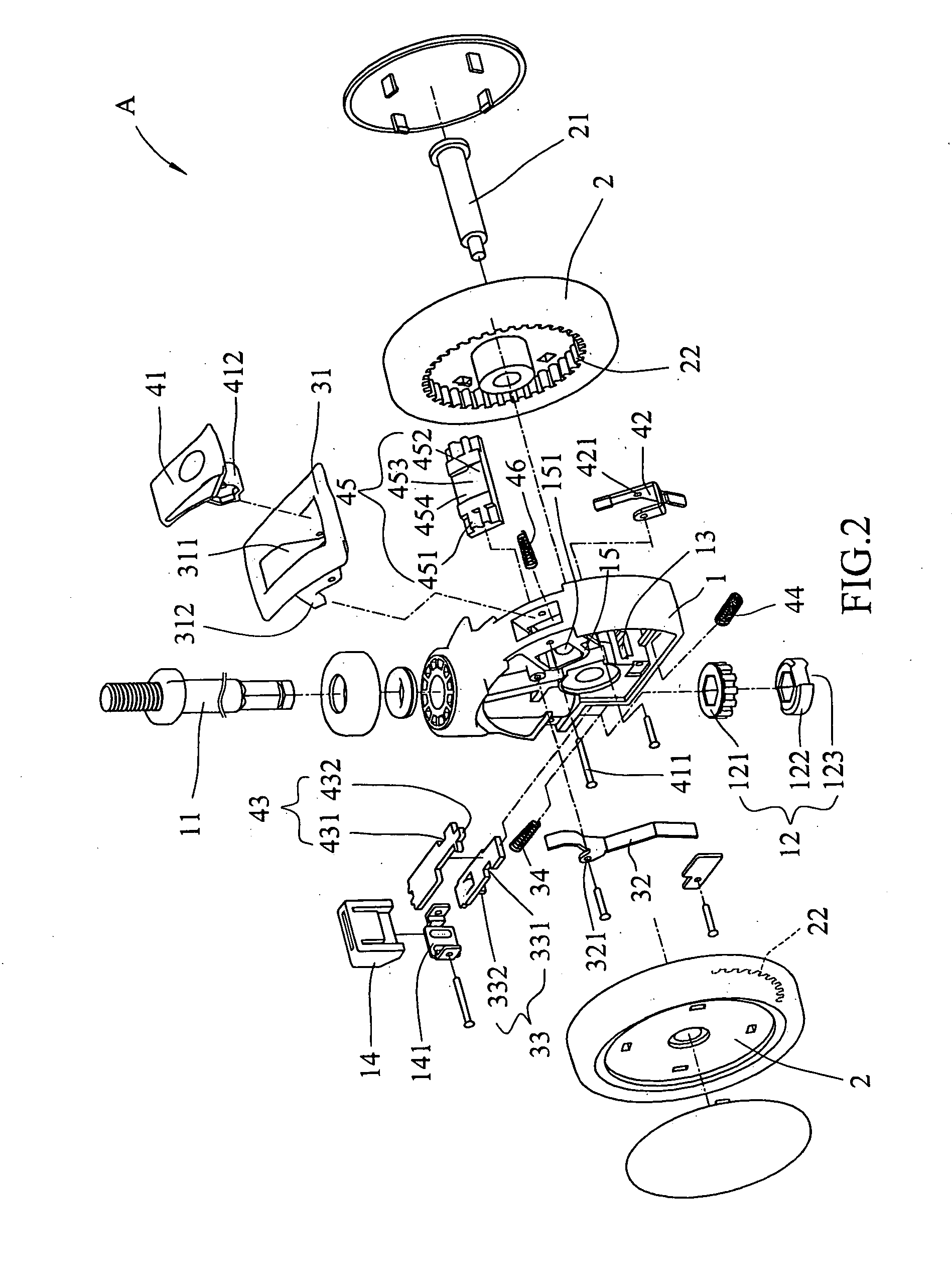
[0017]Referring to FIGS. 1 to 3, the caster “A” of the present invention comprises a casing 1, two wheels 2, a direction unit 3 and a brake unit 4. A shank 11 is radially connected to the casing 1 so that the casing 1 is rotatable about the shank 11, and a locking unit 12 is located at a lower end of the shank 11. The locking unit 12 includes a gear 121 and a direction plate 122. The direction plate 122 includes multiple radial recesses 123 defined in the outer periphery thereof. The number of the radial recesses 123 can be two and located at opposite ends of the diameter of the direction plate 122. A cushion pad 14 is connected to the casing 1 and located outside of the locking unit 12. The cushion pad 14 is connected to a frame 141 fixed to the casing 1.

[0018]The two wheels 2 are connected to two sides of the casing 1 and a shaft 21 extends through the two wheels 2 and the casing 1. An inner gear 22 is connected to each of the two wheels 2.

[0019]The direction unit 3 is located in ...


PUM


Abstract

A caster includes a casing having a shank and a locking unit is located at a lower end of the shank. Two wheels are connected to two sides of the casing by a shaft and an inner gear is connected to each of the two wheels. A direction unit is located in the casing and includes a first lever and an opening, the first lever connects the direction unit to the locking unit. A brake unit is located in the casing and includes a second lever. The second lever connects the brake unit to the locking unit and the inner gears. The second lever is engaged with the opening of the first lever and shares a common pivot with the first lever so as to respectively brake the caster and control direction of the caster.

Description

FIELD OF THE INVENTION[0001]The present invention relates to a caster for bed, desk, furniture or the like and includes a brake unit for braking the caster and a direction unit for setting movement direction.BACKGROUND OF THE INVENTION[0002]A conventional way to move a heavy object such as a bed, a desk or a piece of furniture is to connect multiple wheels at the underside of the object so as to easily move the object. The wheels can move in one direction and cannot turn. The casters are then developed which are able to turn so that the casters provide more convenient functions to the users. Nevertheless, the casters will move when the object is located on an inclined surface and may cause damage to the object. Therefore, a brake unit is installed to the caster so as to brake to prevent moving on an inclined surface. Some casters further have a direction unit which controls the casters to move in the desired direction.[0003]The conventional casters may include one wheel or two wheel...

Claims


Application Information

Patent Timeline
IPC IPC(8): B60B33/00
CPCB60B33/0002B60B33/0007B60B33/0021B60B33/0028B60B33/0042B60B33/0049Y10T16/195B60B33/0068B60B33/0073B60B33/0086B60B33/021B60B33/025B60B33/0057
Inventor CHU, KEIO
Owner CHU KEIO
Why Eureka
Try Eureka