Worm gear and electric power steering apparatus

a technology of electric steering apparatus and gear, which is applied in mechanical devices, gears, transportation and packaging, etc., can solve the problems of increasing the bending stress of the tooth and achieve the effect of further reducing the bending stress of the worm wheel

Inactive Publication Date: 2009-05-14
HITACHI LTD
View PDF14 Cites 26 Cited by
  • Summary
  • Abstract
  • Description
  • Claims
  • Application Information

AI Technical Summary

Benefits of technology

[0004]If the worm wheel includes a part made of resin which meshes with the worm, the bending stress of the worm wheel is further expected to be reduced.
[0005]In view of the foregoing, it is desirable to provide a worm gear and an electric power steering apparatus in which the bending stress of a worm wheel is reduced.

Problems solved by technology

This may cause, depending on specifications of a worm gear, a condition that both of entrance-side and exit-side clearances between a working flank of a worm and a working flank of a worm wheel are large so that the thread of the worm contacts only a central portion, in the direction of tooth trace, of the worm wheel, and thereby cause an increase in bending stress of the tooth of the worm wheel.

Method used


Image

  • Worm gear and electric power steering apparatus
  • Worm gear and electric power steering apparatus
  • Worm gear and electric power steering apparatus

Examples


Embodiment Construction

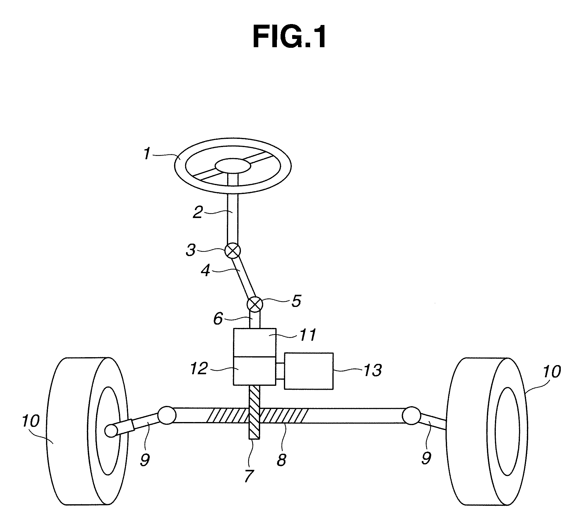
[0024]FIG. 1 schematically shows construction of an electric power steering apparatus of an automotive vehicle according to first and second embodiments of the present invention.

[0025]As shown in FIG. 1, a steering wheel 1 is connected to an upper shaft 2. Upper shaft 2 is connected to a lower shaft 4 via a universal joint 3. Lower shaft 4 is connected to an input shaft 6 via a universal joint 5. Input shaft 6 is connected to a pinion shaft 7. Upper shaft 2, universal joint 3, lower shaft 4, universal joint 5, input shaft 6, and pinion shaft 7 constitute a steering shaft connected between steering wheel 1 and a steered wheel set 10. Pinion shaft 7 meshes with a rack 8. Rack 8 is linked to tie rods 9, 9. Turning movement of steering wheel 1 causes, via pinion shaft 7 and rack 8, tie rods 9, 9 to steer the steered wheel set 10.

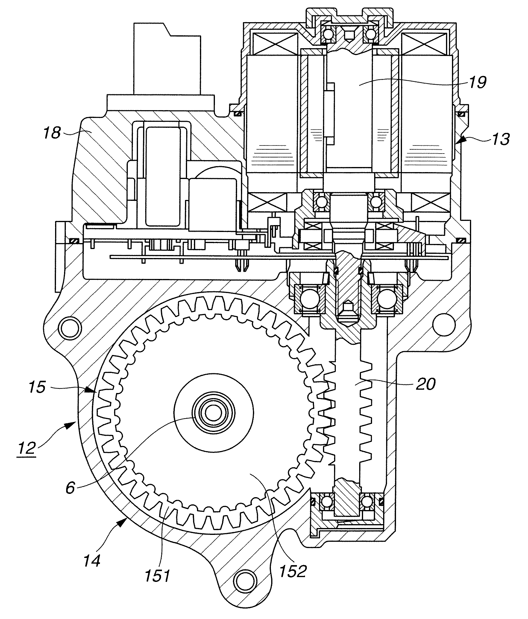
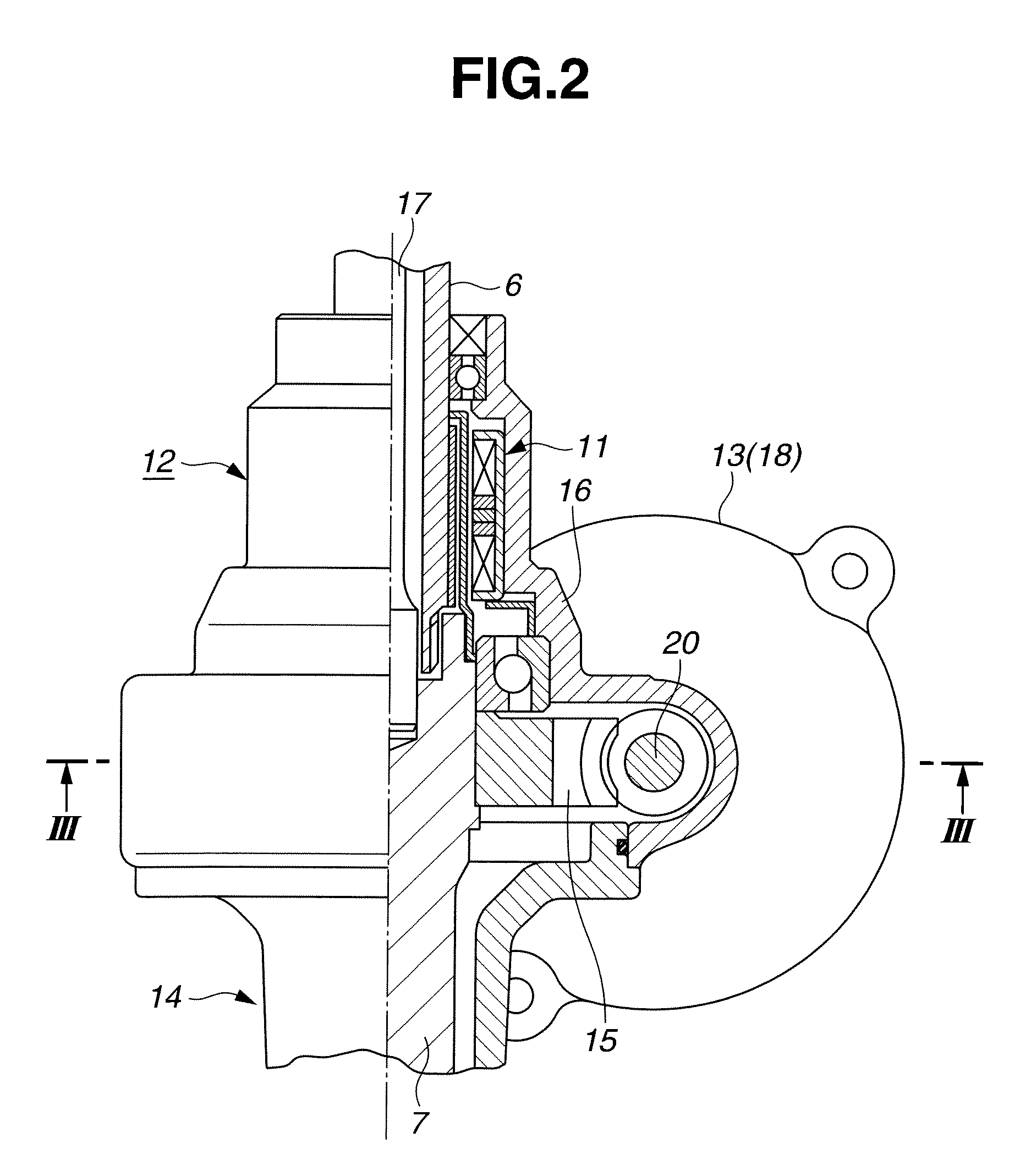
[0026]Input shaft 6 is provided with a torque sensor 11 surrounding the input shaft 6. Torque sensor 11 measures a steering torque applied by a driver to input ...


PUM


Abstract

A worm gear includes a worm shaft including a thread including a tooth flank that defines a concave edge in a tooth profile of the thread; and a worm wheel including a tooth including a tooth flank that defines a convex edge in a tooth profile of the tooth. The worm wheel meshes with the worm shaft in such a manner that the tooth flank of the worm wheel and the tooth flank of the worm shaft, as working flanks, define therebetween an entrance-side clearance as a clearance where the thread of the worm shaft starts to mesh with the tooth of the worm wheel, and an exit-side clearance as a clearance where the meshing terminates, wherein the exit-side clearance is smaller than the entrance-side clearance.

Description

BACKGROUND OF THE INVENTION[0001]The present invention relates to worm gears and electric power steering apparatuses provided with worm gears.[0002]Japanese Utility Model Application Publication No. 4-56250 discloses a worm gear including so called a Niemann worm having a Niemann tooth profile. The Niemann worm includes a thread including a tooth flank that defines an arc-concave edge in a tooth profile of the thread and is positively shifted. The Niemann tooth profile is expected to provide smaller pressure angles, and a larger relative radius of curvature between working flanks, for providing a higher load capacity.SUMMARY OF THE INVENTION[0003]For the Niemann tooth profile, the difference between the thickness of a tooth at the tip and the thickness of the tooth at the root or at the pitch circle tends to be large, because of the arc-concave tooth flanks. This may cause, depending on specifications of a worm gear, a condition that both of entrance-side and exit-side clearances be...

Claims


Application Information

Patent Timeline
Patent Type & Authority Applications(United States)
IPC IPC(8): F16H1/16B62D5/04
CPCB62D5/0406B62D5/0409Y10T74/19828F16H55/0853F16H1/16
Inventor SHIINO, KOHTARO
Owner HITACHI LTD
Why Eureka
Try Eureka