
Exhaust conduit and adapter mounting for portable oxygen concentrator

a technology of exhaust conduit and adapter, which is applied in the direction of combination devices, dispersed particle filtration, and using liquid separation agents, etc., can solve the problems of limited amount of pressurized oxygen, inconvenient and often expensive, and discomfort for patients

Inactive Publication Date: 2009-05-28
CALKINS WADE FR +1
View PDF15 Cites 17 Cited by
  • Summary
  • Abstract
  • Description
  • Claims
  • Application Information

AI Technical Summary

Benefits of technology

"The present invention is a device that helps to direct and redirect the flow of exhaust gases from a portable oxygen concentrator. It includes two u-shaped hollow conduits that are mounted over the exhaust outlets on the oxygen concentrator. The inlet ends of each conduit are designed to fit snugly over the exhaust outlets, allowing hot exhaust gas to flow through the conduits and out through a single outlet. The outflow conduit can be connected to a remote location, providing a safe and efficient way to manage the exhaust gas. The invention helps to improve the performance and safety of portable oxygen concentrators by controlling the flow of exhaust gases."

Problems solved by technology

The drawback was of course that only a limited amount of pressurized oxygen could be stored in a cylinder and so, once used, a cylinder had to be returned to a re-filling facility and re-filled cylinders delivered for use by the patient.
Consequently this was inconvenient and often expensive.
This may cause discomfort for the patient, especially in summer, and may cause the unnecessary use of additional air conditioning to cool the patient's room temperature.

Method used


Image

  • Exhaust conduit and adapter mounting for portable oxygen concentrator
  • Exhaust conduit and adapter mounting for portable oxygen concentrator
  • Exhaust conduit and adapter mounting for portable oxygen concentrator

Examples


Embodiment Construction

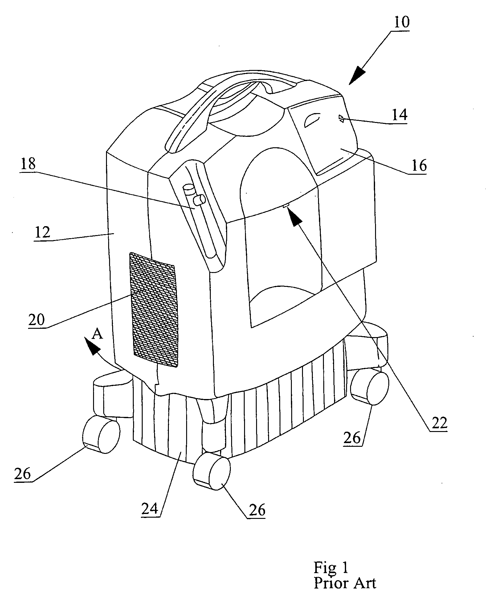
[0021]As seen in FIG. 1, a prior art portable oxygen concentrator 10 has a canister-like upper housing 12 encasing the compressor or compressors, molecular sieves, conduits etc, an on / off power switch 14, operating condition indicators such as LEDs 16, a flow meter 18, an air intake 20 and an oxygen outlet port 22. Housing 12 is mounted on a base 24, supported on a plurality of casters 26.

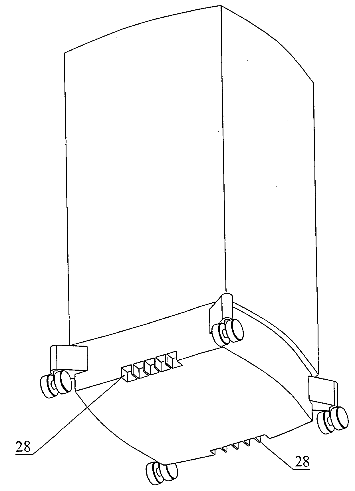
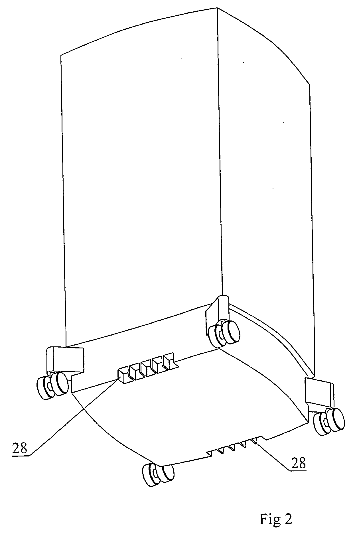
[0022]During operation of the oxygen concentrator, ambient air enters into the oxygen concentrator through air intake 20 and exits both as therapeutic oxygen from oxygen outlet port 22, and as heated exhaust in direction A being forced from exhaust outlets 28. Heated exhaust in direction A is forced from under base 24 in the space between the lower surface of the base and the floor on which the casters rest. The height of the space is governed by the height that casters 26 maintain base 24 above the floor surface. In the past, this design meant that little or nothing could be done to reduce the dis...


PUM

PropertyMeasurementUnit
temperatureaaaaaaaaaa
pressureaaaaaaaaaa
electrically poweredaaaaaaaaaa

Abstract

An exhaust conduit and adapter apparatus for mounting to a pair of exhaust outlets mounted oppositely on the base of a portable oxygen concentrator includes an opposed facing pair of substantially unshaped hollow conduits wherein each conduit has an inlet end and an outlet end. The inlet ends are separated by a distance equal to a separation distance between the pair of exhaust outlets. The outlet ends are mounted to each other in fluid communication with a junction having a single outlet. The inlet ends are adapted for mounting to the pair of exhaust outlets so that, when so mounted, hot exhaust from the oxygen concentrator flows through each conduit and out through the junction and the single outlet of the junction. An outflow conduit is mountable to the single outlet of the junction for outflow of the hot exhaust from the single outlet to a remote location, remote from a patient using the oxygen concentrator.

Description

FIELD OF THE INVENTION[0001]This invention relates to the field of portable oxygen concentrators and in particular to an exhaust conduit and adapter for mounting an exhaust conduit to the exhaust ports of portable oxygen concentrators.BACKGROUND OF THE INVENTION[0002]Many patients require long term therapeutic oxygen treatment whether at home, in nursing homes, or in other settings. In the past it was known to provide pressurized concentrated oxygen in cylinders so that the patient metered oxygen from the cylinder for respiratory support. The drawback was of course that only a limited amount of pressurized oxygen could be stored in a cylinder and so, once used, a cylinder had to be returned to a re-filling facility and re-filled cylinders delivered for use by the patient. Consequently this was inconvenient and often expensive.[0003]More recently, oxygen concentrators capable of concentrating the oxygen from ambient air using pressure swing absorption typically operating between a pa...

Claims


Application Information

Patent Timeline
Patent Type & Authority Applications(United States)
IPC IPC(8): B01D50/00
CPCA61M16/08B01D53/0446B01D53/047B01D2253/10A61M16/101B01D2257/102B01D2259/4533B01D2259/455B01D2256/12
Inventor CALKINS, WADE FRANKCALLDGE, JULIE
Owner CALKINS WADE FR
Learn More