Golf putter assembly

a golf putter and assembly technology, applied in the field of golf clubs, can solve the problems of conventional implements not providing an indication of the amount of data

Inactive Publication Date: 2009-05-28
LIN CHIH CHIEN +1
View PDF8 Cites 64 Cited by
  • Summary
  • Abstract
  • Description
  • Claims
  • Application Information

AI Technical Summary

Benefits of technology

[0006]Therefore, the object of this invention is to provide a golf putter assembly that is able to determine, during a practice swing, what would be an actual golf ball response to an actual swing.
[0007]The golf club assembly of this invention comprises a putter including a head, a display unit disposed in the putter, and a detecting unit disposed in the putter and electrically coupled to the display unit. The detecting unit is operable to detect and record a stationary starting position of a go

Problems solved by technology

However, such conventional implements fail to provide an indication of data associated w

Method used


Image

  • Golf putter assembly
  • Golf putter assembly
  • Golf putter assembly

Examples


Embodiment Construction

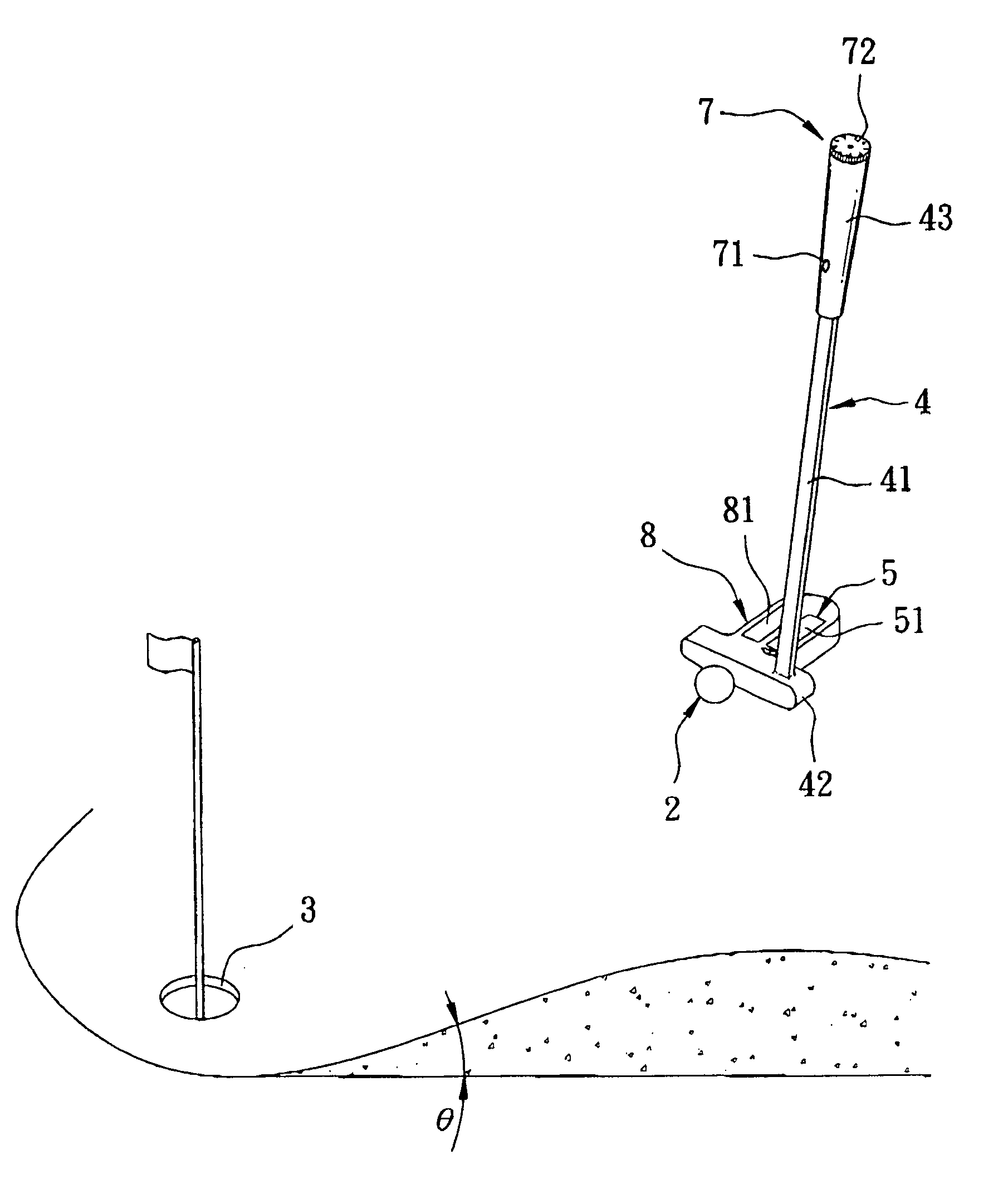
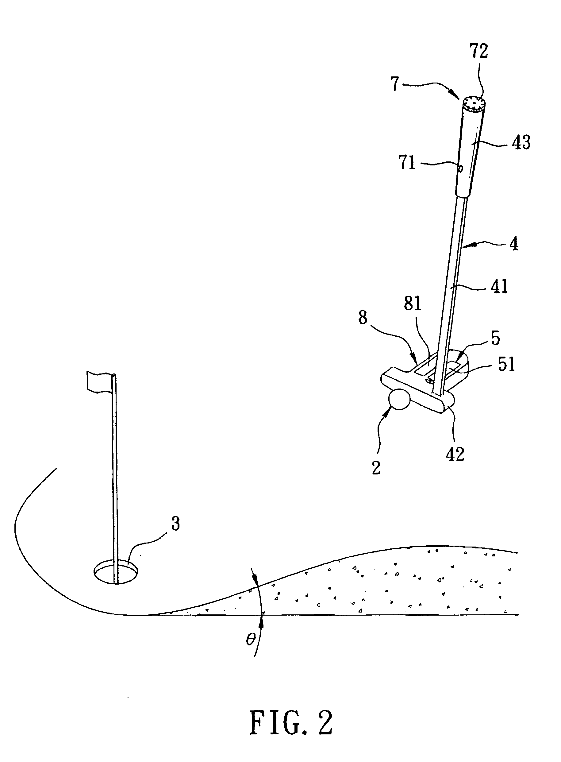
[0014]Referring to FIGS. 2, 3, and 4, a golf putter assembly according to a preferred embodiment of the present invention includes a putter 4, a display unit 5, a detecting unit 6, a user input unit 7, and a power supply unit 8.

[0015]The putter 4 includes a grip 43 that a golfer holds, a head 42 for hitting a golf ball 2, and a shaft 41 that interconnects the grip 43 and the head 42. The golfer swings the putter 4 and strikes the golf ball 2 with the head 42 in an effort to hit the golf ball 2 into a hole 3. The head 42 has a face 421 for hitting the golf ball 2, a sole 423 that is closest to the ground during play, a top surface 422 opposite to the sole 423, a back 424 opposite to the face 421, and an extension 425 that protrudes integrally and rearwardly from the back 424 and that has an upper surface 4251 that is substantially on the same plane as the top surface 422.

[0016]The display unit 5 includes a screen 51 disposed in the extension 425 of the head 42 and at least partly exp...


PUM


Abstract

A golf putter assembly includes a putter including a head, a display unit disposed in the putter, and a detecting unit disposed in the putter and electrically coupled to the display unit. The detecting unit is operable to detect and record a stationary starting position of a golf ball. The detecting unit is further operable to detect, during a practice swing, an instantaneous speed of the head as the head moves past the starting position, and to calculate what would be an initial speed of the golf ball if the golf ball was actually hit by the head with reference to the instantaneous speed of the head detected thereby. The detecting unit further performs control such that the initial speed of the golf ball as calculated is displayed on the display unit.

Description

BACKGROUND OF THE INVENTION[0001]1. Field of the Invention[0002]The present invention relates to a golf club. More particularly, the present invention relates to a golf putter assembly capable of determining, during a practice swing, what would be an actual golf ball response to an actual swing to thereby provide a training effect to golfers.[0003]2. Description of the Related Art[0004]Referring to FIG. 1, a conventional golf club 1 comprises a grip 13 that a golfer holds, a head 12 for hitting a golf ball 2, and a shaft 11 that interconnects the grip 13 and the head 12. The golfer swings the golf club 1, and strikes the golf ball 2 with the head 12 in an attempt to hit the golf ball 2 into a hole 3.[0005]Many training implements have been disclosed that help golfers improve their game. For example, some training implements help golfers improve their putting, such as by indicating the direction the golf ball 2 must travel on a putting green to roll into the hole 3. However, such con...

Claims


Application Information

Patent Timeline
IPC IPC(8): A63B69/36A63B53/04
CPCA63B53/0487A63B53/14A63B69/3685A63B71/0622A63B2071/0602A63B2071/0658A63B2053/0437A63B2220/18A63B2220/20A63B2220/30A63B2220/40A63B2243/0029A63B2220/13A63B60/46A63B2102/32A63B53/0437
Inventor LIN, CHIH-CHIENCHEN, CHIA-HSUN
Owner LIN CHIH CHIEN
Why Eureka
Try Eureka